帧中继配置报告讲解.docx
《帧中继配置报告讲解.docx》由会员分享,可在线阅读,更多相关《帧中继配置报告讲解.docx(21页珍藏版)》请在冰豆网上搜索。
帧中继配置报告讲解
实验八帧中继配置
一、实验目的:
1.理解帧中继交换表的工作原理;
2.理解PVC的概念;
3.掌握帧中继的基本配置;
二、实验环境:
本实验在PC机上利用思科路由模拟软件PacketTracerV5.2进行操作,需要的设备有:
三台2811路由器,三台PC机,一个帧中继空云。
三、实验内容:
1.配置帧中继云;
2.在路由器中配置帧中继协议;
3.配置动态路由协议RIP。
四、实验步骤:
1.规划网络拓扑
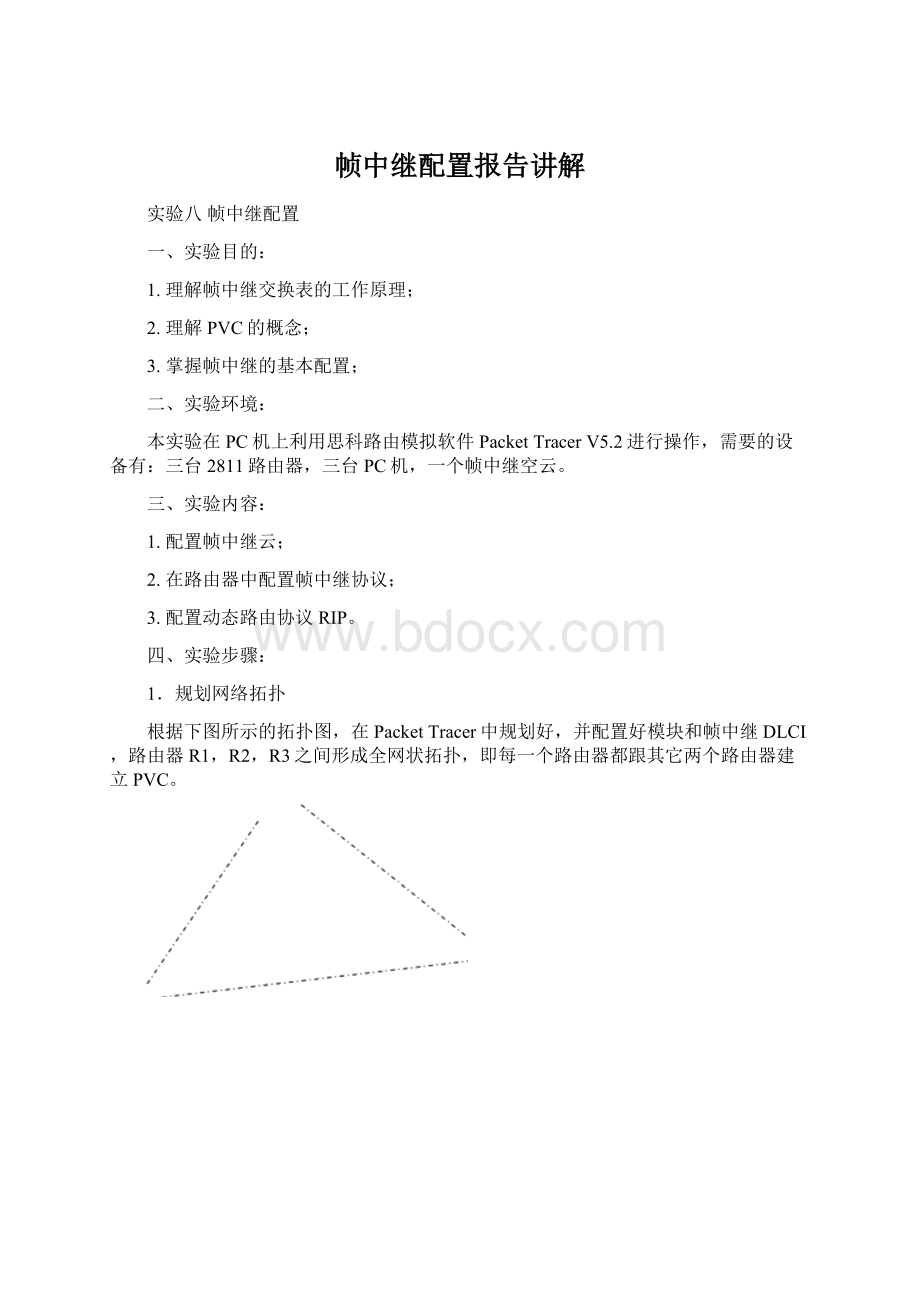
根据下图所示的拓扑图,在PacketTracer中规划好,并配置好模块和帧中继DLCI,路由器R1,R2,R3之间形成全网状拓扑,即每一个路由器都跟其它两个路由器建立PVC。
图8-1实验拓扑图
(1)添加3台2811路由器,为三个路由器分别添加S端口模块(NM-4A/S模块)。
图8-2为路由器添加模块
(2)添加一个Cloud-PT-Empty设备(Cloud0)模拟帧中继网络,为Cloud0添加3个S端口模块(PT-CLOUD-NM-1S模块),用来与路由器进行连接。
图8-3为云设备添加模块
(3)连接各个设备:
路由器作为DTE设备,Cloud0作为DCE设备
(4)按照拓扑添加3台PC机作测试用,连接到路由器F0/0端口,并启动各连接端口,为各PC设置好IP和网关。
2.配置帧中继网络
(1)设置帧中继云Cloud0的S1,S2,S3三个接口的DLCI值:
图8-4配置Serial1接口
图8-5配置Serial2接口
图8-6配置Serial3接口
(2)请写出在真实的帧中继交换机中对Serial3接口进行配置(如图8-6所示)的相关命令:
interfaceSerial3
noipaddress
encapsulationframe-relay
clockrate56000
framelmi-typeansi
frame-relayintf-typedce
frame-relayroute301interfaces1103
frame-relayroute302interfaces2203
(3)配置帧中继云Cloud0的地址映射表:
图8-7配置帧中继地址映射
(4)如果是在真实的帧中继交换机中进行地址映射,请写出实现上图中帧中继地址映射表的相关配置命令。
interfaceSerial1
frame-relayroute103interfaces3301
frame-relayroute102interfaces2201
interfaceSerial2
frame-relayroute201interfaces1102
frame-relayroute203interfaces3302
interfaceSerial3
frame-relayroute301interfaces1103
frame-relayroute302interfaces2203
3.配置3台路由器的帧中继协议:
(1)在R1路由器上进行帧中继配置,配置两个子接口,分别与R2,R3建立PVC,参考配置命令如下:
R1(config)#ints1/0
R1(config-if)#noshut
R1(config-if)#encapsulationframe-relay
R1(config-if)#frame-relaylmi-typecisco
R1(config)#ints1/0.1point-to-point//配置子接口,并设置为点对点模式
R1(config-subif)#ipadd192.168.1.1255.255.255.0//分配子接口ip地址
R1(config-subif)#frame-relayinterface-dlci102
//指定点对点对应的DLCI值
R1(config-subif)#exit
R1(config)#ints1/0.2point-to-point
R1(config-subif)#ipadd192.168.2.1255.255.255.0
R1(config-subif)#frame-relayinterface-dlci103
R1(config-subif)#exit
(2)按照路由器R1的配置方法,对R2路由器进行配置,配置命令为:
R2(config)#ins1/0
R2(config-if)#noshut
R2(config-if)#encapsulationframe-relay
R2(config-if)#frame-relaylmi-typeciaco
R2(config-if)#exit
R2(config)#ins1/0.1point-to-point
R2(config-subif)#ipadd192.168.1.2255.255.255.0
R2(config-subif)#frame-relayinterface-dlci201
R2(config-subif)#exit
R2(config)#ins1/0.2point-to-point
R2(config-subif)#ipadd192.168.3.1255.255.255.0
R2(config-subif)#frame-relayinterface-dlci203
R2(config-subif)#exit
(3)按照路由器R1的配置方法,对R3路由器进行配置,配置命令为:
R3(config)#ins1/0
R3(config-if)#noshut
R3(config-if)#encapsulationframe-relay
R3(config-if)#frame-relaylmi-typecisco
R3(config-if)#exit
R3(config)#ins1/0.1point-to-point
R3(config-subif)#ipadd192.168.3.2255.255.255.0
R3(config-subif)#frame-relayinterface-dlci302
R3(config-subif)#exit
R3(config)#ins1/0.2point-to-point
R3(config-subif)#ipadd192.168.2.2255.255.255.0
R3(config-subif)#frame-relayinterface-dlci301
R3(config-subif)#exit
(4)在路由器R1上使用showframe-relaymap,查看帧中继地址映射表。
记录结果为:
4.在三台路由器上配置F0/0端口
R1(config)interfacefastEthernet0/0
R1(config-if)#ipaddress192.168.10.1255.255.255.0
R1(config-if)#noshutdown
R1(config-if)#exit
R2(config)interfacefastEthernet0/0
R2(config-if)#ipaddress192.168.20.1255.255.255.0
R2(config-if)#noshutdown
R2(config-if)#exit
R3(config)interfacefastEthernet0/0
R3(config-if)#ipaddress192.168.30.1255.255.255.0
R3(config-if)#noshutdown
R3(config-if)#exit
5.配置RIP路由协议
(1)在路由器R1上启动rip路由协议,相关配置命令为:
R1(config)#routerrip
R1(config-router)#net192.168.10.0
R1(config-router)#net192.168.1.0
R1(config-router)#net192.168.2.0
R1(config-router)#exit
(2)在路由器R2上启动rip路由协议,相关配置命令为:
R2(config)#routerrip
R2(config-router)#net192.168.20.0
R2(config-router)#net192.168.1.0
R2(config-router)#net192.168.3.0
R2(config-router)#exit
(3)在路由器R3上启动rip路由协议,相关配置命令为:
R3(config)#routerrip
R3(config-router)#net192.168.2.0
R3(config-router)#net192.168.3.0
R3(config-router)#net192.168.30.0
R3(config-router)#exit
(4)在路由器R1上查看路由表,记录结果为:
(5)测试PC1,PC2,PC3主机之间的连通性。
PC3:
PC2:
PC1:
(6)把图8-6中的LMI类型修改为ANSI,请测试PC1与PC2,PC1与PC3之间的连通性。
PC3
PC2
即各主机之间均不能通讯。
(7)应修改哪一台设备的配置,做如何修改才能使PC3与其它PC机之间实现连通?
答:
修改cloud0的配置,将LMI的类型改为ansi类型,即能实现PC之间的连通。
(8)通过步骤(7),可以得出什么结论?
答:
路由器与帧中继两端的LMI类型要一致,才能实现通讯。
五、思考与练习
(1)不使用子接口的配置方式实现本实验。
路由器R1,R2,R3上均不配置子接口。
R1:
interfaceFastEthernet0/0
ipaddress192.168.10.1255.255.255.0
interfaceSerial1/0
ipaddress192.168.1.1255.255.255.0
encapsulationframe-relay
frame-relaymapip192.168.1.2112broadcast
frame-relaymapip192.168.1.3113broadcast
routerrip
network192.168.1.0
network192.168.10.0
R2:
interfaceFastEthernet0/0
ipaddress192.168.20.1255.255.255.0
interfaceSerial1/0
ipaddress192.168.1.2255.255.255.0
encapsulationframe-relay
frame-relaymapip192.168.1.1112broadcast
frame-relaymapip192.168.1.3213broadcast
routerrip
network192.168.1.0
network192.168.20.0
R3:
interfaceFastEthernet0/0
ipaddress192.168.30.1255.255.255.0
interfaceSerial1/0
ipaddress192.168.1.3255.255.255.0
encapsulationframe-relay
frame-relaymapip192.168.1.1113broadcast
frame-relaymapip192.168.1.2213broadcast
routerrip
network192.168.1.0
network192.168.30.0
连通性:
PC1:
PC2:
(2)请用点对多点的子接口配置方式实现本实验。
在路由器R1中配置点对多点子接口,路由器R2和R3使用物理接口分别与R1中的两个子接口建立PVC。
R1:
interfaceFastEthernet0/0
ipaddress192.168.10.1255.255.255.0
!
interfaceSerial1/0
noipaddress
encapsulationframe-relay
!
interfaceSerial1/0.1point-to-point
ipaddress192.168.1.1255.255.255.0
frame-relayinterface-dlci103
!
interfaceSerial1/0.2point-to-point
ipaddress192.168.2.1255.255.255.0
frame-relayinterface-dlci102
!
routerrip
network192.168.1.0
network192.168.2.0
network192.168.10.0
R2:
interfaceFastEthernet0/0
ipaddress192.168.20.1255.255.255.0
interfaceSerial1/0
ipaddress192.168.2.2255.255.255.0
encapsulationframe-relay
frame-relayinterface-dlci201
routerrip
network192.168.2.0
network192.168.20.0
R3:
interfaceFastEthernet0/0
ipaddress192.168.30.1255.255.255.0
interfaceSerial1/0
ipaddress192.168.1.2255.255.255.0
encapsulationframe-relay
frame-relayinterface-dlci301
routerrip
network192.168.1.0
network192.168.30.0
测试连通性:
PC2pingPC1:
PC3pingPC1
 升级会员
升级会员 