ie3d教程chap8.docx
《ie3d教程chap8.docx》由会员分享,可在线阅读,更多相关《ie3d教程chap8.docx(24页珍藏版)》请在冰豆网上搜索。
ie3d教程chap8
Chapter8MagneticCurrentModelingofApertureStructures
Sofar,wehavebeendiscussingthemodelingofelectriccurrentinelectroniccircuits.Basically,weareusingpolygonstorepresenttheelectricconductorsandwearesolvingthecurrentdistributionontheelectricconductors.Therearecircuitsorantennasthatutilizingslotsinelectricconductorstoachievespecificperformances.Forsuchcircuitsorantennas,itwouldbebettertomodelthetangentialelectricfieldacrosstheslotsinsteadofthecurrentdistributionontheelectricconductors,becausetheareaofslotsismuchsmallerthantheareaoftheconductors,andthecomputationaleffortwillbesignificantlysmaller.Theoretically,tangentialelectricfieldacrossaslotisequivalenttothemagneticcurrentontheslot.Wewillcallsuchamodelasmagneticcurrentmodel.
Inthischapter,wewilldemonstratehowwecanapplythemagneticcurrentmodelingtosolvesomeproblemsefficiently.MagneticcurrentmodelingisonlyavailableonIE3DPowerPack.ForthoseuserswhoseIE3Dlicensesdonothavethemagneticcurrentcapability,youcanchoosetoskipthischapteroryoucanfollowitforpractice.FollowingtheexamplescanstillhelpyoutopracticeeditingonMGRID.ForthoseIE3Dlicenseswithoutthemagneticcurrentcapability,nosimulationinvolvingmagneticcurrentisallowedevenyoucanstillbuilditonMGRID.Therefore,youwouldnotbeabletocreatethecurrentdistributionfile.
Fromtheelectromagnetictheory,theslotelectricfieldisequivalenttothefictitiousmagneticcurrentdistributionbyEquation(8-1).
Jm=E⨯n(8-1)
whereJmistheequivalentmagneticcurrentdensity;Eisthetangentialelectricfieldonaslot;nistheunitnormalvectoroftheslot.Ausershouldunderstandthatthemagneticcurrentmodelisbasedupontheassumptionthattheslotisonaflat,largeandverygoodelectricconductor.Inreality,theelectricconductorisalwaysfiniteanditsconductivityisalwaysfinite.Theaccuracyofthemodelwilldependuponhowbigthegroundplaneisandhowgoodtheelectricconductoris.
Section1.ModelingaSlotAntennawithCPW-feedorGapPortFeed.
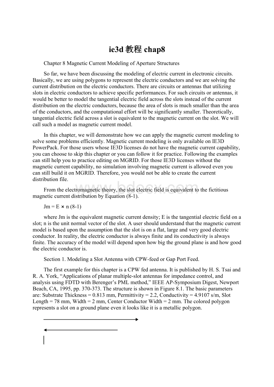
ThefirstexampleforthischapterisaCPWfedantenna.ItispublishedbyH.S.TsaiandR.A.York,“Applicationsofplanarmultiple-slotantennasforimpedancecontrol,andanalysisusingFDTDwithBerenger’sPMLmethod,”IEEEAP-SymposiumDigest,NewportBeach,CA,1995,pp.370-373.ThestructureisshowninFigure8.1.Thebasicparametersare:
SubstrateThickness=0.813mm,Permittivity=2.2,Conductivity=4.9107s/m,SlotLength=78mm,Width=2mm,CenterConductorWidth=2mm.Thecoloredpolygonrepresentsaslotonagroundplaneevenitlookslikeitisametallicpolygon.
78mm
Figure8.1ACPW-fedslotantennatobeanalyzedusingmagneticcurrentmodeling.
Buildingthepolygontorepresenttheslotshouldbesimplewithwhatyouhavelearned.Therearemultiplewaystobuildit.Youcanbuildtheslotasapath.Youcanalsobuildtheoutershapeasarectangleof78mmby6mm.Then,youbuildasmallerrectangleof74mmby2mmonanotherlayer.YoucanusethesmallerrectangletobuildholeonthebiggerrectanglefortheshapeinFigure8.1.Certainly,youwillneedtodosomeextraworktodefinetheports1and2anditsproximity.Thestructureispre-builtandsavedinfile:
.\ie3d\samples\slot.geo.WewillconcentrateourdiscussiononthesubstratesetupandtheLayerWindow.Figure8.2showsthelayout,theLayerWindowandtheBasicParameters.YoumaynoticewehavedefinedtwosubstratelayersatZ=0.813.Basically,thesubstratesetupmeansthefollowing:
From-∞to0isair.From0to0.813mmisthesubstrate.From0.813to0.813mmisthegroundplane.Then,from0.813mmto∞isairagain.
ItisnotallowedtobuildafinitethickgroundsubstratelayeronIE3Datthistime.However,youcandefineonenormalsubstratelayerbetween2infinitelythingroundplanestomodelthefinitethickgroundplane.
OntheLayerWindow,youseeahorizontaldashlineacrosstheNo.1LayeratZ=0.81300.Itmeansthatthepolygonlayerisaninterfaceofgroundplane.Any2Dpolygononitisassumedtobeaslotontheground.Thepolygonsonthelayouteditormeantheareatobeetchedawayfromthegroundplane.
Figure8.2Thestructure,theLayerWindowandtheBasicParametersdialog.
WehavedefinedadifferentialpairofExtensionforMMICportonit.FormagneticcurrentmodelingExtensionforMMICschemeandtheAdvancedExtensionschemearethesame.Thequestionis,whatdoesthedifferentialpairmean?
Ifthepolygonsaremetallicpolygons,thedifferentialpairmeansitisapairofcoupledstrip.Formagneticcurrentmodeling,thedifferentialpairmeansitisaCPW.WewillexplainthereasoninSection2.
Figure8.3Theslotantennafedbyahorizontallocalizedport.
Isthistheonlychoiceforaportonmagneticcurrentmodeling?
Itcertainlyisnot.Savedin.\ie3d\samples\slot1.geoisthesamegeometryfedbyaHorizontalLocalizedport.
AHorizontalLocalizedportisbasicallyagapport.Ifthepolygonsaremetallicpolygons,thestructureinFigure8.3meansafoldeddipolewithagapportbetweenthetwoterminals.Forthemagneticcurrentmodeling,thepolygonsrepresentslotsontheground.TheHorizontalLocalizedportmeansanexcitationacrossthegapattheportlocation.MoreexplanationcanbefoundinSection2.
HowcanwedefinetheHorizontalLocalizedportonit?
Itissimple.
Step1RunMGRID.Open.\ie3d\samples\slot1.geo.SelectPort->DeleteAllPorts.Wewillseethestructureconsistsoftwopolygons(seeFigure8.4).Polygon2isthe“foldeddipole”whilethepolygon1isarectanglewithbothendsconnectedtotheendsofthe“foldeddipole”.
Figure8.4Theslot1.geowithouttheportdefined.
Figure8.5TheHorizontalLocalizedPortdefinitiondialog.
TherearetwowayswecandefinetheHorizontalLocalizedportonit.Wearegoingtoshowthebothways.
Step2SelectEdit->SelectPolygonGroup.Windowtherectangle1toselectit.SelectPort->SelectedRectanglesforHorizontalLocalizedPort.MGRIDwillpromptyoutheHorizontalLocalizedPortdefinitiondialog.Itdetectstwopossibledirectionsfortheport.Wewantthepositiveterminaltobeatthelefthandsideofthegapandthenegativeterminaltobeattherighthandsideofthegap(seeFigure8.3).Weshouldchoosethe2ndPhi=180degree.Pleasenoteyoumaybepromptedwith“1stPhi=180and2ndPhi=0”inyourrun.YoushouldchoosetheonecorrespondingtoethePhi=180.SelectOKtocontinue.WewillgettheportdefinedasshowninFigure8.3.
Ifitisforelectriccurrent,theportdefineasourcetoapplyavoltagebetweenthepositiveterminalandthenegativeterminal.Formagneticcurrentmodeling,thereisanambiguityfortheportdirection.WewilldiscussthisissuelaterinSection2.Let’strythedifferentwaytodefinetheHorizontalLocalizedPort.
Step3TheHorizontalLocalizedPortschemehasbeenimplementedafewyearsago.ThewaytodefineanHorizontalLocalizedPortwejustdemonstratedwastheonlyway.However,manyusersdonotrealizetheexistenceofsuchaschemebecausethewayofdefiningitisdifferentfromotherschemes.Forthisreason,wehaveimplementedawayclosertodefiningportsinotherschemes.
PleaseselectPort->DeleteAllPortstodeletetheportagain.SelectPort->PortforEdgeGroup.TheDe-EmbeddingSchemedialogcomesup(seeFigure8.6).PleasechooseHorizontalLocalized.SelectOKtocontinue.
Figure8.6TheDe-EmbeddingSchemedialogwithHorizontalLocalizedschemeselected.
Figure8.7Thecomparisonoftheslotantennawith2differentports.
Step4Pleasewindowthepolygon1inFigure8.4.MGRIDwillpromptyoufortheHorizontalLocalizedPortDefinitiondialoginFigure8.5.Selectthe2ndPhi=180degreesandselectOK.MGRIDwilldefinetheHorizontalLocalizedportonslot1.geo.SelectPort->ExitPorttoexitthemode.Pleasesimulateandcomparethes-andz-parametersoftheslot.geoandslot1.geo(seeFigure8.7).Thes-parametersarealmostthesameexceptthereissomesmalldifferenceatthedip.Thereissomeslightshiftinthez-parametercurves.Itisduetothefactthatthedifferenceinthefeedproximitycausessomedifferenceinthereactancepartintheimpedance.
Section2.DiscussionofPortsonSlotStructures.
InSection1,wehavediscussedhowtomodelaslotantennausingdifferentialfeedschemes.However,whatarethemeaningsoftheschemesdiscussed.Inthissection,wewillillustratethedifferentports.
Inthe.\ie3d\practice\slot.geo,weareusingdifferentialExtensionforMMICport(seeFigure8.2).Infact,the“+1”portisapplyingavoltagebetweenthemetalonitsrightsidetothemetalonitsleftside.The“-1”portisapplyingavoltagebetweenthemetalonitsleftsidetothemetalonitsrightside.ItisequivalenttoapplyingavoltagebetweenthecenterconductorandthetwosideconductorsontheCPWstructure(seeTable8.1).Basically,thetwopolygonsarerepresentingthetwoslotsofCPW.
Inthe.\ie3d\practice\slot1.geo,weareusingtheHorizontalLocalizedport(seeTable8.1).Whatitmeansisthatweareapplyingavoltageacrossthegap.Itisequivalenttoagapportintheelectriccurrentmodel.
Certainly,thefeedproximityisdifferentbetweenCPWfeedandtheGapPortfeedwhenwemodeltheslotantenna.ItisnotsurprisingthattheymayyieldslightdifferentresultsinFigure8.7.
Someusersareconsideringwhetherwecandefineasingle-endedportonapolygonformagneticcurrentmodeling.Theyareconsideringthatthesingle-endedportin“ExcitationacrossaGap”inTable8.1
 升级会员
升级会员 