基于FPGA的语音数字时钟系统.docx
《基于FPGA的语音数字时钟系统.docx》由会员分享,可在线阅读,更多相关《基于FPGA的语音数字时钟系统.docx(17页珍藏版)》请在冰豆网上搜索。
基于FPGA的语音数字时钟系统
基于FPGA的语音数字时钟系统设计
1.设计要求:
(1)计时功能:
这是那个计时器设计的大体功能,每隔一分钟记一次时刻并在屏幕上显示出当前时刻。
(2)闹钟功能:
若是当前时刻与设置的闹钟时刻相同,则扬声器会发出报时声音。
(3)设置新的计时器时刻:
用户用数字键0~9输入新的时刻,然后按下TIME健确认。
(4)设置新的闹钟时刻:
用户用数字键0~9输入新的闹钟时刻,然后按下ALARM健确认。
(5)显示所设置的闹钟时刻:
在正常记时显示状态下,用户直接按下ALARM健,则显示器上显示已经设置好的闹钟时刻。
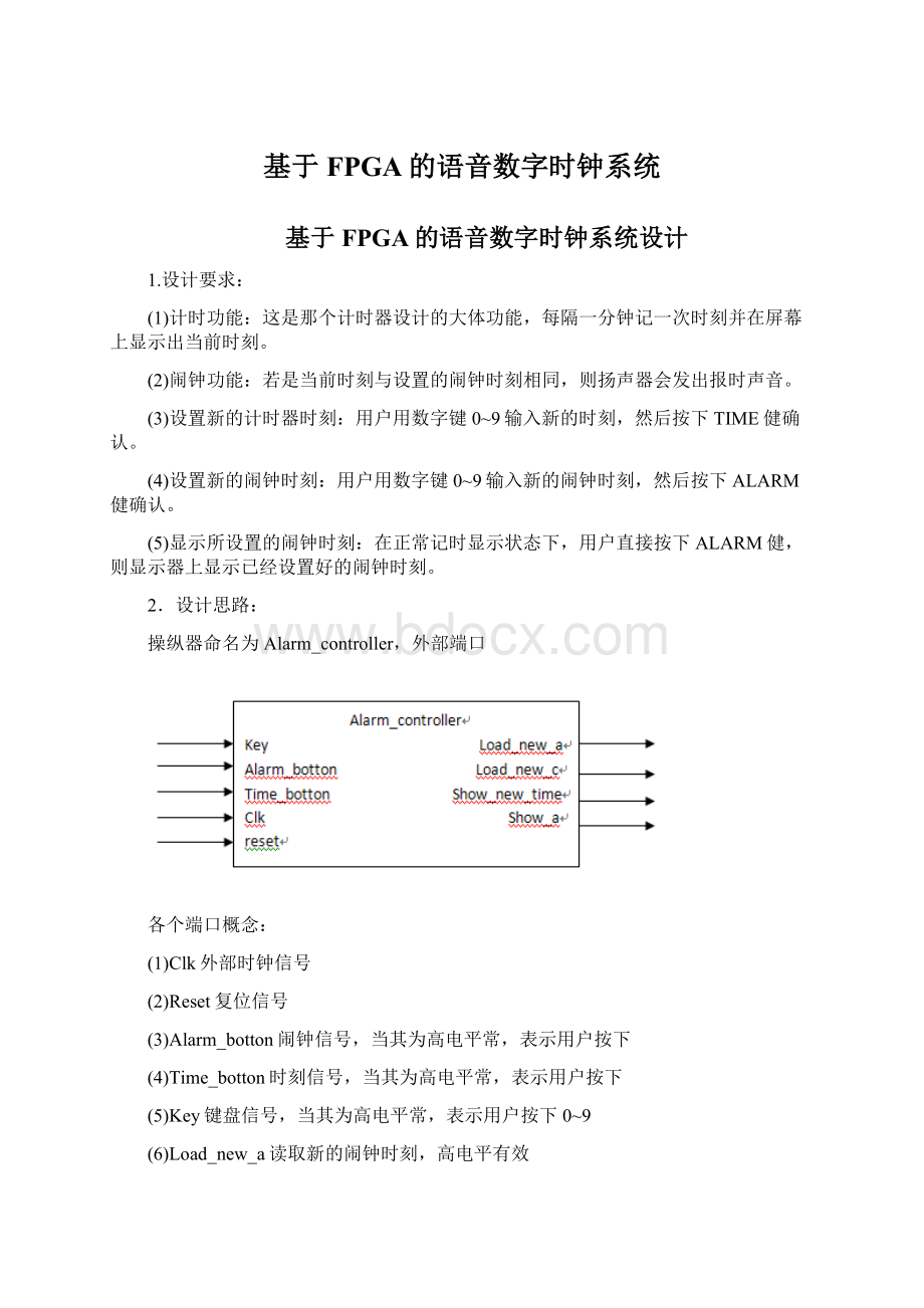
2.设计思路:
操纵器命名为Alarm_controller,外部端口
各个端口概念:
(1)Clk外部时钟信号
(2)Reset复位信号
(3)Alarm_botton闹钟信号,当其为高电平常,表示用户按下
(4)Time_botton时刻信号,当其为高电平常,表示用户按下
(5)Key键盘信号,当其为高电平常,表示用户按下0~9
(6)Load_new_a读取新的闹钟时刻,高电平有效
(7)Load_new_c操纵设置新的时刻,高电平有效
(8)Show_new_time读取并显示新的时刻,高电平有效
(9)Show_a当Show_new_time为低电平常,依照Show_a操纵当前是显示闹钟时刻仍是时钟时刻
依照端口的设置和操纵要求,设定如下5个状态
S0:
闹钟正常计数状态
S1:
键盘输入状态,当用户按下键盘,即进入此状态,当一段时刻后用户没有按下Alarm或Time确认,则自动返回S0状态
S2:
设定闹钟状态,当用户按完键盘,按下Alarm键时进入此状态
S3:
设按时刻状态,当用户按完键盘,按下Time键时进入此状态
S4:
显示闹钟时刻,当用户直接按下Alarm键时,进入此状态
在S4状态下,用户按下Alarm键时钟即显示闹钟时刻,通过一段延时以后,时钟从头恢复S0状态。
以下是程序流程表
当前状态
控制输入
下一状态
控制输出
S0
Key=’1’
S1
Show_new_time<=’1’
Alarm_botton=’1’
S2
Show_a<=’1’
else
S0
Null
S1
Key=’1’
S1
Show_new_time<=’1’
Alarm_botton=’1’
S2
Load_new_a<=’1’
Time_botton=’1’
S3
Load_new_c<=’1’
超时
是
S0
Null
否
S1
Show_new_time<=’1’
S2
Alarm_botton=’1’
S2
Load_new_a<=’1’
else
S0
Null
S3
Time_botton=’1’
S3
Load_new_c<=’1’
else
S0
Null
S4
Alarm_botton=’1’
S4
Show_a
超时
是
S0
Null
否
S4
Show_a并等待
程序:
程序包P_alarm封装概念
libraryIEEE;
useP_alarmis
subtypet_digitalisintegerrange0to7;
subtypet_shortisintegerrange0to65535;
typet_clock_timeisarray(3downto0)ofT_digital;
typet_displayisarray(3downto0)ofStd_logic_vector(6downto0);
typeseg7isarray(0to7)ofStd_logic_vector(6downto0);
constantSeven_seg:
seg7:
=("0000000001",--0
"0000000010",--1
"0000000100",--2
"0000001000",--3
"0000010000",--4
"0000100000",--5
"0001000000",--6
"00",--7
"00",--8
"00",--9);
endpackageP_alarm;--程序包体封装终止
libraryIEEE;
useAlarm_contorlleris
port(Key,Alarm_botton,Time_botton,clk,reset:
instd_logic;
Load_new_a,Load_new_c,Show_new_time,Show_a:
outstd_logic);
endAlarm_controller;
ARCHITECTUREartofAlarm_controlleris
typet_stateis(s0,s1,s2,s3,s4);--5种工作状态
constantkey_timeout:
t_short:
=900;--键盘延不时刻
constantshow_alarm_timeout:
t_short:
=900;--alarmjianyanshi900ns
signalcurr_state:
t_state;--zhuangtaijidangqianzhuangtaiwei
signalnext_state:
t_state;--zhuangtaijixiayigongzuowei
signalcounter_k:
t_state;--jianpan
signalenable_count_k:
std_logic;--jianpanchaoshiyunxu
signalcount_k_end:
std_logic;--jianpanchaoshi
signalcounter_a:
t_short;--alarmjian
signalenable_count_a:
std_logic;--alarmjianchaoshiyunxu
signalcount_a_end:
std_logic;--alarmjianchaoshijieshu
begin
p0:
process(clk,reset)
begin
ifreset='1'then
curr_state<=s0;
elsifrising_edge(clk)then
curr_state<=next_state;
endif;
endprocess;
p1:
process(Key,Alarm_botton,Time_botton,curr_state,count_a_end,count_k_end)
begin--geigegeshuchufuchushizhi
next_state<=curr_state;
load_new_a<='0';
load_new_c<='0';
show_a<='0';
show_new_time<='0';
enable_count_k<='0';
enable_count_a<='0';
casecurr_stateis
whens0=>
if(Key='1')then
next_state<=s1;
Show_new_time<='1';
elsif(Alarm_botton<='1')then
next_state<=s2;
Show_a<='1';
else
next_state<=s0;
null;
endif;
whens1=>
if(key='1')then
next_state<=s1;
Show_new_time<='1';
elsif(Alarm_botton<='1')then
next_state<=s2;
Load_new_a<='1';
elsif(Time_botton<='1')then
next_state<=s3;
Load_new_c<='1';
else
if(count_k_end='1')then
next_state<=s0;
null;
else
next_state<=s1;
Show_new_time<='1';
endif;
enable_count_k<='1';
endif;
whens2=>
if(Alarm_botton<='1')then
next_state<=s2;
Load_new_a<='1';
else
next_state<=s0;
null;
endif;
whens3=>
if(Time_botton<='1')then
next_state<=s3;
Load_new_c<='1';
else
next_state<=s0;
null;
endif;
whens4=>
if(Alarm_botton<='1')then
next_state<=s4;
else
if(count_a_end='1')then
next_state<=s0;
null;
else
next_state<=s4;
Show_a<='1';
endif;
enable_count_a<='1';
endif;
whenothers=>
null;
endcase;
endprocess;
Count_key:
process(Enable_count_k,clk)
begin
if(Enable_count_k<='0')then
Counter_k<='0';
count_k_end<='0';
elsif(rising_edge(clk))then
if(counter_k>=key_tinmeout)then
count_k_end='1';
else
counter_k<=Counter_k+1;
endif;
endif;
endprocessCount_key;
Count_alarm:
process(Enable_count_a,clk)
begin
if(enable_count_a<='1')then
counter_a<='0';
count_a_end<='0';
elsif(rising_edge(clk))then
if(counter_a>=show_alarm_timeout)then
count_a_end<='1';
else
counter_a<=counter_a+1;
endif;
endif;
endprocessCount_alarm;
endart;
二.闹钟系统译码器设计
1.设计思路:
每次按下闹钟系统的数字键盘后产生一个数字所对应的10位二进制数据信号转换为1位十进制整数信号,作为小时,分钟计数的4个数字之一。
结构图
Decoder
输入
0000000001
0000000010
0000000100
0000001000
0000010000
输出
0
1
2
3
4
输入
0000100000
0001000000
00
00
00
输出
5
6
7
8
9
libraryIEEE;
usedecoderis
port(keypad:
instd_logic_vector(9downto0);
value:
outT_digital);
enddecoder;
ARCHITECTUREartofdecoderis
begin
withkeypadselect
value<=0when"0000000001",
1when"0000000010",
2when"0000000100",
3when"0000001000",
4when"0000010000",
5when"0000100000",
6when"0001000000",
7when"00",
8when"00",
9when"00",
0whenothers;
endart;
三.闹钟系统的移位寄放器的设计
1.设计思路:
在clk的上升沿同步下,将key端口的输入信号移入new_time端口的输出端口最低位,原有信息一次向左移动,最高位舍去,reset对输出端口new_time异步清零。
电路原理图
libraryIEEE;
usekey_bufferis
port(key:
int_digital;
clk,reset:
instd_logic;
new_time:
outt_clock_time);
endkey_buffer;
ARCHITECTUREartofkey_bufferis
signaln_t:
t_clock_time;
process(clk,reset)
begin
if(reset<='1')then
n_t<=(0,0,0,0);
elsif(rising_edge(clk))then
foriin3downto1loop--zuohuanyi
n_t(i)<=n_t(i-1);
endloop;
n_t(0)<=key;
endif;
endprocess;
new_time<=n_t;
endart;
四.闹钟寄放器的设计
1.设计思路:
闹钟寄放器在时钟上升沿同步下,依照Load_new_a端口的输入信号操纵Alarm_time口的输出,当操纵信号为高电平常,把New_alarm_time端口的赋给alarm_time然后输出,reset端口输入信号对alarm_time端口的输出进行异步清零复位。
电路原理图
libraryIEEE;
useAlarm_regis
port(clk,reset:
instd_logic;
new_alarm_time:
int_clock_time;
load_new_a:
instd_logic;
alarm_time:
outstd_logic);
endAlarm_reg;
ARCHITECTUREartofAlarm_regis
begin
process(clk,reset)
begin
if(reset='1')then
alarm_clock<=(0,0,0,0);
else
ifrising_edge(clk)then
ifload_new_a='1'then
alarm_time<=new_alarm_time;
elsifload_new_a='0'then
assertfalsereport"uncertainload_new_alarmcontrol"
severitywarning
endif;
endif;
endif;
endprocess;
endart;
五.时刻计数器的设计
1.设计思路:
时刻计数器在时钟上升沿同步下,依照load_new_c端口的输入操纵信号操纵current_time口的输出,当操纵信号为高电平常,把new_current_time端口的值赋给current_time进行输出。
当reset端口为高电平常,对current_time端口进行清零操作。
Reset的优先级高于load_new_c,且当reset,load_new_c同时为低电平常,在时钟上升沿处,对current_time端口输出信号进行累加一次加1,并依照小时,分钟的进位规律进位。
Alarm_counter
libraryIEEE;
useAlarm_counteris
port(load_new_c:
instd_logic;
clk,reset:
instd_logic;
new_current_time:
int_clock_time;
current_time:
outt_clock_time);
endAlarm_counter;
ARCHITECTUREartofAlarm_counteris
signali_current_time:
t_clock_time;
begin
process(clk,reset)
variablec_t:
t_clock_time;
ifreset='1'then
i_current_time<=(0,0,0,0);
elsifload_new_c<='1'then
i_current_time<=new_current_time;
elsifrising_edge(clk)then
ifc_t(0)<=9then
c_t(0):
=c_t(0)+1;
else
c_t(0):
=0;
ifc_t
(1)<6then
c_t
(1):
=c_t
(1)+1;
else
c_t
(1):
=0;
ifc_t(3)<2then
ifc_t
(2)<=9then
c_t
(2):
=c_t
(2)+1;
else
c_t
(2):
=0;
c_t(3):
=c_t(3)+1;
endif;
elsec_t
(2)<3then
c_t
(2):
=c_t
(2)+1;
else
c_t
(2):
=0;
c_t(3):
=0;
endif;
endif;
endif;
endif;
i_current_time<=c_t;
endif;
endprocess;
current_time<=i_current_time;
endart;
六.闹钟系统显示驱动器
1.设计思路:
当show_new_time输入为高电平常,依照new_time端口输入的时刻数据,产生相应的4个七段数码显示器的驱动数据,并在display端口输出该信号;当show_new_time为低电平常,判定show_a端口的输入电平,若是为高电平,则依照alarm_time端口输入的时刻数据,产生相应的4个七段数码显示器的驱动数据,并也在display端口输出。
若show_a也为低电平,依照current_time端口的输入信号,对display端口驱动。
当alarm_time端口的输入信号值与current_time端口的输入信号值相同时,sound_alarm端口的输出信号有效。
反之无效
Display_driver
libraryIEEE;
usedisplay_driveris
port(new_time:
int_clock_time;
current_time:
int_clock_time;
alarm_time:
int_clock_time;
show_new_time:
instd_logic;
show_a:
instd_logic;
display:
outt_display;
sound_alarm:
outstd_logic);
enddisplay_driver;
ARCHITECTUREartofdisplay_driveris
signaldisplay_time:
t_clock_time;
begin
process(new_time,alarm_time,current_time,show_new_time,show_a)
begin
sound_loop:
foriinalarm_time'rangeloop
if(current_time(i)=alarm_time(i))then
sound_alarm<='1';
else
sound_alarm<='0';
endif;
endloopsound_loop;
ifshow_new_time<='1'then
display_time<=new_time;
elsifshow_a<='1'then
display_time<=alarm_time;
elsifshow_a<='0'then
display_time<=current_time;
else
assertfalsereport"uncertaindisplay_drivercontrol!
"
severitywaring;
endif;
endprocess;
disp:
process(display_time)
begin
foriindisplay_time'rangeloop
display(i)<=seven_seg(display_time(i))
endloop;
endprocess;
endart;
七.闹钟分频器
1.设计思路:
分频器,将clk_in的输入信号通过度频后交与clk_out当reset端口为高电平常,clk_out输出清零。
Fq_divider
libraryIEEE;
usefq_divideris
port(clk_in,reset:
instd_logic;
clk_out:
outstd_logic);
endfq_divider;
ARCHITECTUREartoffq_divideris
constantdivide_period:
t_short:
=6000;
begin
process(clk_in,reset)
variablecnt:
t_short;
begin
if(reset='1')then
cnt:
=0;
clk_out<='0';
elsifrising_edge(clk)then
if(cnt<(divide_period/2))then
clk_out<='1';
cnt:
=cnt+1;
elsif(cnt<(divide_period-1))then
clk_out<='0'
cnt:
=cnt+1;
else
cnt:
=0;
endif;
endif;
endprocess;
endart;
八.闹钟的整体组装
1.设计思路:
前面已经把闹钟的各个模块别离进行了编译封装,此刻开始整体组装。
由于键盘解码和闹钟移位寄放器是一体的,且输出新的时刻或闹钟值,因此二者连为一体,再者,由于闹钟移位寄放器输出的新数据可能是时刻值也可能是闹钟值,因此输出口一分为2,别离接入时刻计数器,闹钟寄放器,又由于闹钟移位寄放器所输出的值要显示在led上,因此输出再引出一根线接到显示模块上。
分
 升级会员
升级会员 