CATIA线框曲面造型旋钮 knob.docx
《CATIA线框曲面造型旋钮 knob.docx》由会员分享,可在线阅读,更多相关《CATIA线框曲面造型旋钮 knob.docx(19页珍藏版)》请在冰豆网上搜索。
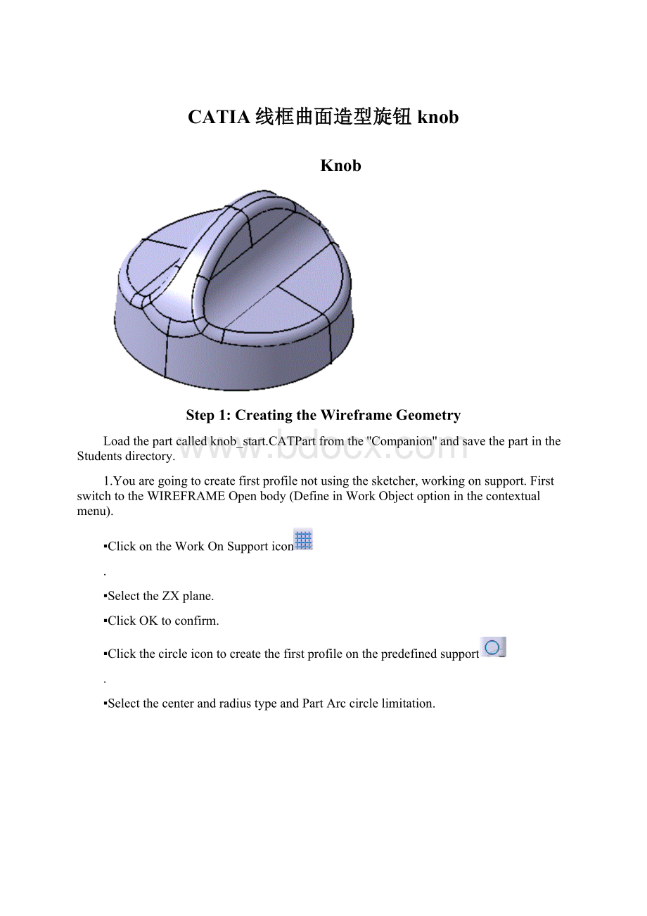
CATIA线框曲面造型旋钮knob
Knob
Step1:
CreatingtheWireframeGeometry
Loadthepartcalledknob_start.CATPartfromthe''Companion''andsavethepartintheStudentsdirectory.
1.Youaregoingtocreatefirstprofilenotusingthesketcher,workingonsupport.FirstswitchtotheWIREFRAMEOpenbody(DefineinWorkObjectoptioninthecontextualmenu).
▪ClickontheWorkOnSupporticon
.
▪SelecttheZXplane.
▪ClickOKtoconfirm.
▪Clickthecircleicontocreatethefirstprofileonthepredefinedsupport
.
▪SelectthecenterandradiustypeandPartArccirclelimitation.
▪Createthecenterpoint“onthefly”clickingtheCenterPointfield:
▪Selectthe“coordinates”pointtypeandkeyinX=0,Y=0andZ=0.
▪Keyintheradius64mm,thestartangle–90degandtheendangle0deg:
▪ClickOKtoconfirmthefirstprofilecreation.
▪ExittheWorkOnSupportmodedeletingtheworkingsupportinthespecificationtree:
2.Youaregoingtocreatesecondprofilenotusingthesketcher,workingonsupport.
▪ClickontheWorkOnSupporticon
.
▪SelecttheYZplane.
▪ClickOKtoconfirm.
▪Clickthecircleicontocreatethefirstprofileonthepredefinedsupport
.
▪SelectthecenterandradiustypeandPartArccirclelimitation.
▪Createthecenterpoint“onthefly”clickingtheCenterPointfield:
▪Selectthe“coordinates”pointtypeandkeyinX=30,Y=50andZ=0.
▪Keyintheradius20mm,thestartangle190degandtheendangle260deg:
▪ClickOKtoconfirmthesecondprofilecreation.
▪Deletethesupportinthetree.
3.Youwillnowcreatethethirdprofileusingthesketcher.
▪SelecttheSketchericon
andselecttheYZplane.
▪Selectthelineicon
anddrawthislinewithitsconstraints:
▪Exitthesketcher.Thethirdprofileiscreated.
Step2:
CreatingtheBasicSurfaces
4.Youaregoingtocreatetwoextrudedsurfaces.
▪ClickontheExtrudeicon
.
▪Selecttheprofile1andkeyintheseparameters:
▪ClickOKtoconfirmthefirstsurfacecreation.
▪ClickontheExtrudeicon
.
▪Selecttheprofile2andkeyintheseparameters:
▪ClickOKtoconfirmthefirstsurfacecreation.
5.Youaregoingtocreatetherevolutionsurface.
▪ClickontheRevolutionicon
.
▪Selectthethirdprofileandkeyintheseparameters(axis:
verticalaxisofthesketch):
▪ClickOKtoconfirm.Allthebasicsurfacesarecreated.
Step3:
PerformingOperationstheBasicSurfaces
6.Youaregoingtotrimthefirstextrudedsurfaceandtherevolutionsurface.
▪Clickonthetrimicon
.
▪Selectthefirstextrudedsurfaceandtherevolutionsurface:
▪Usingthe“Othersideelement1”and“Othersideelement2”button,aimtoobtainthis:
▪ClickOKtoconfirmthetrimcreation.
7.Youaregoingtosplitthesecondextrudedsurfacewiththepreviouslycreatedtrim.
▪Clickonthespliticon
.
▪Selecttheextrudedsurfaceaselementtocut,andthetrimascuttingelement.
▪Playingwiththe“Otherside”button,aimtoobtainthis:
▪ClickOKtoconfirmthesplitcreation.
8.Youaregoingtoextrapolatethepreviouslycreatedsplitsurface.
▪Clickontheextrapolateicon
.
▪Selectthesplitsurfacelowerboundary.
▪Selectthesplitsurface.
▪Selectthe“uptoelement”extrapolationtype.
▪Selectthetrimsurfaceandactivatethe“Assembleresult”button:
▪ClickOKtoconfirmtheextrapolatecreation.
9.Youaregoingtoextrapolatethepreviouslycreatedextrapolatesurface.
▪Clickontheextrapolateicon
.
▪Selecttheextrapolatedsurfacehigherboundary.
▪Selectthesplitsurface.
▪Selectthe“uptoelement”extrapolationtype.
▪Selectthetrimsurfaceandactivatethe“Assembleresult”button:
▪ClickOKtoconfirmthesecondextrapolatedsurfacecreation.
10.Youaregoingtotrimthepreviouslycreatedextrapolatesurfacewiththefirstcreatedtrimsurface.
▪Clickonthetrimicon
.
▪Selectthelastcreatedextrapolatedsurfaceandthefirstcreatedtrim.
▪Usingthe“Othersideelement1”and“Othersideelement2”button,aimtoobtainthis:
▪ClickOKtoconfirm.
11.Youaregoingtocreateavariablefiletonthepreviouslycreatedtrim.
▪Clickonthevariableradiusfilleticon
.
▪Selectthisedgeandkeyintheradius10mm:
▪Double-clickontheleftradiusvalueandkeyin20mm:
▪ClickOKtoconfirm.Yougetthis:
▪ClickOKtoconfirmthefilletcreation:
12.Youaregoingtocreateanedgefiletonthepreviouslycreatedsurface.
▪Clickontheedgefilleticon
.
▪Selectthisedgeandkeyintheradius5mm:
▪ClickOKtoconfirmthefilletcreation:
13.Youaregoingtocreatethesymmetricsurfaceandjointhetwosurfaces.
▪Clickonthesymmetryicon
.
▪SelectthepreviouslycreatedsurfaceaselementtosymmetrizeandtheYZplaneasreference:
▪ClickOKtoconfirm.
▪Clickonthejoinicon
.
▪SelecttheEdgeFillet.2surfaceandtheSymmetry.1surface.
▪ClickOKtoconfirmthejoinoperation.
14.Youaregoingtocreatethesymmetricsurfacefromthepreviousjoinandjointhetwosurfaces.
▪Clickonthesymmetryicon
.
▪SelectthepreviouslycreatedjoinaselementtosymmetrizeandtheZXplaneasreference:
▪ClickOKtoconfirm.
▪Clickonthejoinicon
andselecttheJoin.1surfaceandtheSymmetry.2surface.
▪ClickOKtoconfirmthejoincreation.
Theoperationsonthesurfacesareallperformed.Youshouldgetthis:
Step4:
AnalyzingandModifyingthedraftangle
15.Youaregoingtoanalyzethedraft.
▪ClickontheDraftAnalysisicon.
▪
Changetothecustomizedviewmode:
▪SelecttheJoin.2.
▪Changethedraftvaluestoobtain:
▪Closethedraftanalysiscolorbar.
16.Thenmodifythedraftangle.
▪DoubleclickontheSketch.1inthetree:
yougetinthesketch.
▪Modifythelineinclinationfrom90deginto86deg:
▪Exitthesketch.Thepartisautomaticallyupdated:
Step5:
Offsettingasolid
17.Youaregoingtocreateasolidfromthepreviouslycreatedsurface.
▪SelectStart/MechanicalDesign/PartDesign.
▪SelecttheJoin.2.
▪SelecttheThickSurfaceicon
.
▪VerifytheThickarrowspointinginwardasshownbelow:
▪Keyin4mmintheFirstOffsetValuefield.
▪ClickOKtoconfirmthesolidcreation.
▪HidetheOpenBodycontainingallthesurfaceelements.
18.Thenyouaregoingtosplitthesolidtomakeitsbottomfaceplane.
▪ChangethevisualizationmodetoWireframe:
▪Selecttheleftviewicon:
▪Zoomontheleftbottomtocheckthatthebottomofthepartisnomoreplane.
▪ComebacktoaShadingvisualizationmode.
▪PuttheXYplaneina‘’Show’’mode.
▪Selectthespliticon.
▪SelecttheXYplaneasSplittingelement.
▪ClickOKtoconfirmthesplitcreation.
19.Now,applyamaterialonthethicksurface:
▪SelecttheApplyMaterialicon.
▪SelecttheRubbermaterialunderthe‘‘other’’tabofthemateriallibrary.
▪Draganddropitontheknob,clickonOKtoconfirm.
 升级会员
升级会员 