项目8 数字电压表设计.docx
《项目8 数字电压表设计.docx》由会员分享,可在线阅读,更多相关《项目8 数字电压表设计.docx(10页珍藏版)》请在冰豆网上搜索。
项目8数字电压表设计
项目八数字电压计设计
班级:
09电信姓名:
曾珍学号:
33
1.实训目标
1)使用AD0809模数转换芯片实现信号转换。
2)在EDA-V+系统上实现交通灯控制系统。
2.实训步骤
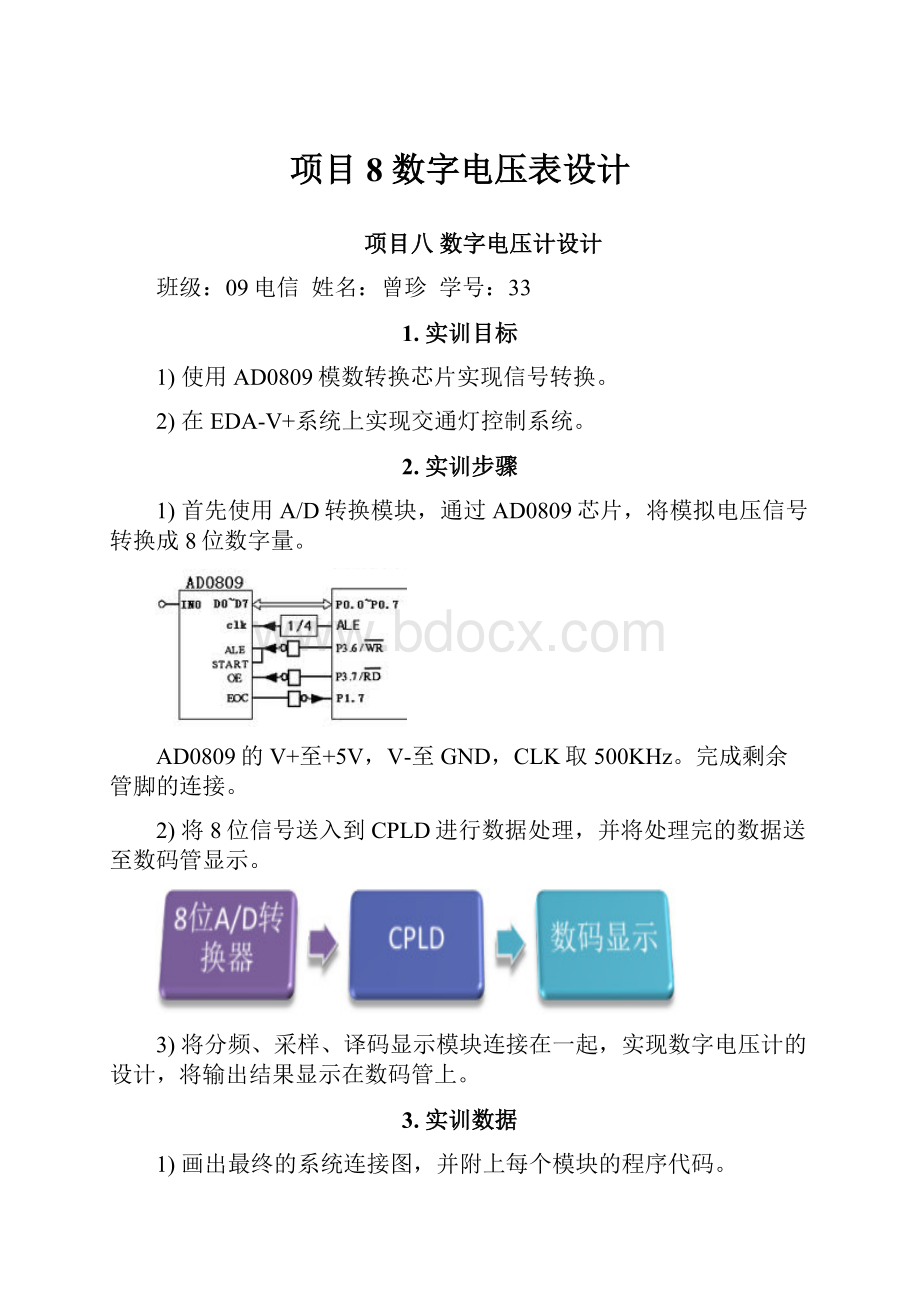
1)首先使用A/D转换模块,通过AD0809芯片,将模拟电压信号转换成8位数字量。
AD0809的V+至+5V,V-至GND,CLK取500KHz。
完成剩余管脚的连接。
2)将8位信号送入到CPLD进行数据处理,并将处理完的数据送至数码管显示。
3)将分频、采样、译码显示模块连接在一起,实现数字电压计的设计,将输出结果显示在数码管上。
3.实训数据
1)画出最终的系统连接图,并附上每个模块的程序代码。
division1
libraryieee;
useieee.std_logic_1164.all;
useieee.std_logic_unsigned.all;
entitydivision1is
port(
clk:
instd_logic;
clk4:
outstd_logic);
enddivision1;
architecturebehaveofdivision1is
begin
process(clk)
variablecounter:
std_logic_vector(7downto0);
begin
if(clk'eventandclk='0')then
if(counter=250)then
counter:
="00000000";
clk4<='1';
else
counter:
=counter+'1';
clk4<='0';
endif;
endif;
endprocess;
endbehave;
code
libraryieee;
useieee.std_logic_1164.all;
useieee.std_logic_unsigned.all;
useieee.std_logic_arith.all;
entitycodeis
port(clk:
instd_logic;
datain:
inunsigned(7downto0);
scan:
outstd_logic_vector(1downto0);
dataout1:
outstd_logic_vector(6downto0)
);
endcode;
architecturebehaveofcodeis
signalcnt:
integerrange2downto0;
signaldata:
integerrange9downto0;
signaltemp1:
integerrange511downto0;
signaltemp2:
integerrange99downto0;
signalcount1,count2:
integerrange9downto0;
signalcount3:
integerrange5downto0;
begin
process(clk)
begin
ifclk'eventandclk='1'then
ifcnt=2thencnt<=0;
else
cnt<=cnt+1;
endif;
endif;
endprocess;
process(datain)
begin
temp1<=conv_integer(datain)+conv_integer(datain);
casetemp1is
when500to511=>
count3<=5;temp2<=temp1-500;
when400to499=>
count3<=4;temp2<=temp1-400;
when300to399=>
count3<=3;temp2<=temp1-300;
when200to299=>
count3<=2;temp2<=temp1-200;
when100to199=>
count3<=1;temp2<=temp1-100;
when0to99=>
count3<=0;temp2<=temp1;
whenothers=>null;
endcase;
casetemp2is
when90to99=>
count2<=9;count1<=temp2-90;
when80to89=>
count2<=8;count1<=temp2-80;
when70to79=>
count2<=7;count1<=temp2-70;
when60to69=>
count2<=6;count1<=temp2-60;
when50to59=>
count2<=5;count1<=temp2-50;
when40to49=>
count2<=4;count1<=temp2-40;
when30to39=>
count2<=3;count1<=temp2-30;
when20to29=>
count2<=2;count1<=temp2-20;
when10to19=>
count2<=1;count1<=temp2-10;
when0to9=>
count2<=0;count1<=temp2;
whenothers=>null;
endcase;
endprocess;
process(cnt)
begin
casecntis
when0=>data<=count1;scan<="00";
when1=>data<=count2;scan<="01";
when2=>data<=count3;scan<="10";
whenothers=>null;
endcase;
endprocess;
process(data)
begin
casedatais
when0=>dataout1<="0111111";
when1=>dataout1<="0000110";
when2=>dataout1<="1011011";
when3=>dataout1<="1001111";
when4=>dataout1<="1100110";
when5=>dataout1<="1101101";
when6=>dataout1<="1111101";
when7=>dataout1<="0000111";
when8=>dataout1<="1111111";
when9=>dataout1<="1101111";
whenothers=>null;
endcase;
endprocess;
endbehave;
ad
libraryieee;
useieee.std_logic_1164.all;
useieee.std_logic_arith.all;
entityadis
port(busy:
instd_logic;
datain:
inunsigned(7downto0);
clk:
instd_logic;
dataout:
outunsigned(7downto0);
cs:
outstd_logic;
rd:
outstd_logic
);
endad;
architecturebehavofadis
begin
process(clk)
variablecount:
unsigned(1downto0);
begin
ifclk'eventandclk='1'then
casecountis
when"00"=>
cs<='1';
rd<='1';
dataout<=datain;
when"01"=>
cs<='0';
rd<='0';
when"11"=>
ifbusy='0'then
count:
=count-1;
endif;
whenothers=>
null;
endcase;
count:
=count+1;
endif;
endprocess;
endbehav;
2)记录下系统的外部连线,注明每个管脚的功能。
芯片EP1K30TC144-3
26~33接datain[7..0]---------输入
54接busy----------------------
55接clk------------------------脉冲信号500khz
92~86接dataout1[6..0]------输出接到数码管显示数字信号
98,99接scan[1..0]------------扫描
101接cs
102接rd
芯片0809
Busy接
Int接54busy
D0~d7接26~33接datain[7..0]
Vref+接vcc
Vref-接gnd
In0接试验箱滑阻
Cs接101cs
Rd接101rd
3)本设计中的数字电压计的最小测量电压值是多少?
拿一块数字万用表同时进行测量,比较数字电压计的误差,并记录相应数据。
4.附AD0809芯片资料
1)芯片结构
2)信号选择段
 升级会员
升级会员 