Lab 71 Configuring Switches for IP Telephony Support.docx
《Lab 71 Configuring Switches for IP Telephony Support.docx》由会员分享,可在线阅读,更多相关《Lab 71 Configuring Switches for IP Telephony Support.docx(38页珍藏版)》请在冰豆网上搜索。
Lab71ConfiguringSwitchesforIPTelephonySupport
Lab7-1ConfiguringSwitchesforIPTelephonySupport
LearningObjectives
•ConfigureautoQoStosupportIPphones
•ConfigureCoSoverridefordataframes
•ConfigurethedistributionlayertotrustaccesslayerQoSmeasures
•ManuallyconfigureCoSfordevicesthatcannotspecifyCoS(camera)
•ConfigureHSRPforvoiceanddataVLANStoensureredundancy
•Configure802.1QtrunksandEtherChannelsforLayer2redundancyandload
balancing
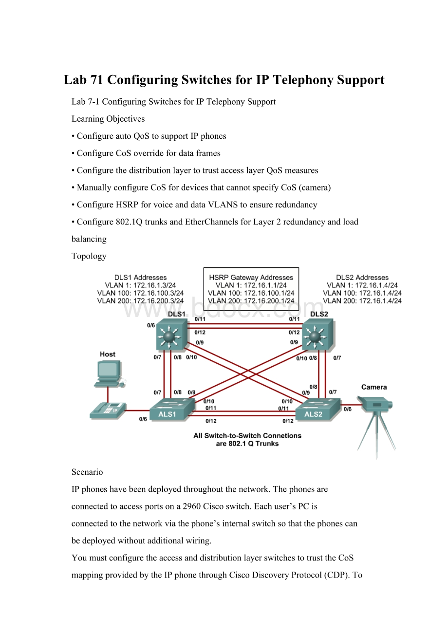
Topology
Scenario
IPphoneshavebeendeployedthroughoutthenetwork.Thephonesare
connectedtoaccessportsona2960Ciscoswitch.Eachuser’sPCis
connectedtothenetworkviathephone’sinternalswitchsothatthephonescan
bedeployedwithoutadditionalwiring.
YoumustconfiguretheaccessanddistributionlayerswitchestotrusttheCoS
mappingprovidedbytheIPphonethroughCiscoDiscoveryProtocol(CDP).To
2-22CCNP:
BuildingMultilayerSwitchedNetworksv5.0-Lab7-1Copyright©2006,CiscoSystems,Inc
ensureredundancyforthephonesanduserendstations,youmustuseHSRP
onthedistributionlayerswitches.
Acameraforvideoisalsodeployedonthenetwork,whichrequiresthatits
accessportonthe2960bemanuallyconfigured.Itisnotnecessarytohavea
cameratosuccessfullycompletethelab.
Step1
Poweruptheswitchesandusethestandardprocessforestablishinga
HyperTerminalconsoleconnectionfromaworkstationtoeachswitchinyour
pod.
PrepareforthelabbyremovingallpreviousVLANinformationand
configurations.RefertoLab2.0,“ClearingaSingleSwitch,”orLab2.0b,
“ClearingaSwitchConnectedtoaLargerNetwork.”
Step2
Cablethelabaccordingtothediagram.
ConfigurethemanagementIPaddressesinVLAN1,andthehostname,
password,andtelnetaccessonallfourswitches.
Youalsoneedtoconfigureadefaultgatewayontheaccesslayerswitches.The
distributionlayerswitchesactasLayer3devicesanddonotneeddefault
gateways.
Switch#configureterminal
Enterconfigurationcommands,oneperline.EndwithCNTL/Z.
Switch(config)#hostnameALS1
ALS1(config)#enablesecretcisco
ALS1(config)#linevty015
ALS1(config-line)#passwordcisco
ALS1(config-line)#login
ALS1(config-line)#exit
ALS1(config)#interfacevlan1
ALS1(config-if)#ipaddress172.16.1.101255.255.255.0
ALS1(config-if)#noshutdown
ALS1(config-if)#exit
ALS1(config)#ipdefault-gateway172.16.1.1
ALS1(config)#end
Switch#configureterminal
Enterconfigurationcommands,oneperline.EndwithCNTL/Z.
Switch(config)#hostnameALS2
ALS2(config)#enablesecretcisco
ALS2(config)#linevty015
ALS2(config-line)#passwordcisco
ALS2(config-line)#login
ALS2(config-line)#exit
ALS2(config)#interfacevlan1
ALS2(config-if)#ipaddress172.16.1.102255.255.255.0
3-22CCNP:
BuildingMultilayerSwitchedNetworksv5.0-Lab7-1Copyright©2006,CiscoSystems,Inc
ALS2(config-if)#noshutdown
ALS2(config-if)#exit
ALS2(config)#ipdefault-gateway172.16.1.1
ALS2(config)#end
Switch#configureterminal
Enterconfigurationcommands,oneperline.EndwithCNTL/Z.
Switch(config)#hostnameDLS1
DLS1(config)#enablesecretcisco
DLS1(config)#linevty015
DLS1(config-line)#passwordcisco
DLS1(config-line)#login
DLS1(config-line)#exit
DLS1(config)#interfacevlan1
DLS1(config-if)#ipaddress172.16.1.3255.255.255.0
DLS1(config-if)#noshutdown
DLS1(config-if)#end
Switch#configureterminal
Enterconfigurationcommands,oneperline.EndwithCNTL/Z.
Switch(config)#hostnameDLS2
DLS2(config)#enablesecretcisco
DLS2(config)#linevty015
DLS2(config-line)#passwordcisco
DLS2(config-line)#login
DLS2(config-line)#exit
DLS2(config)#interfacevlan1
DLS2(config-if)#ipaddress172.16.1.4255.255.255.0
DLS2(config-if)#noshutdown
DLS2(config-if)#end
Step3
Configurethetrunksaccordingtothediagram,andconfigureEtherChannels
betweentheswitches.UsingEtherChannelforthetrunksprovidesLayer2load
balancingoverredundanttrunks.
ThefollowingisasampleconfigurationforthetrunksandEtherChannelfrom
DLS1totheotherthreeswitches.Noticethatthe3560needstheswitchport
trunkencapsulation{dot1q|isl}command,becausethisswitchalsosupports
ISLencapsulation.
DLS1#configureterminal
Enterconfigurationcommands,oneperline.EndwithCNTL/Z.
DLS1(config)#interfacerangefastethernet0/7-8
DLS1(config-if-range)#switchporttrunkencapsulationdot1q
DLS1(config-if-range)#switchportmodetrunk
DLS1(config-if-range)#channel-group1modedesirable
Creatingaport-channelinterfacePort-channel1
DLS1(config-if-range)#interfacerangefastethernet0/9-10
DLS1(config-if-range)#switchporttrunkencapsulationdot1q
DLS1(config-if-range)#switchportmodetrunk
DLS1(config-if-range)#channel-group2modedesirable
Creatingaport-channelinterfacePort-channel2
 升级会员
升级会员 