有限元软件应用计算实例.docx
《有限元软件应用计算实例.docx》由会员分享,可在线阅读,更多相关《有限元软件应用计算实例.docx(9页珍藏版)》请在冰豆网上搜索。
有限元软件应用计算实例
有限元软件应用计算实例
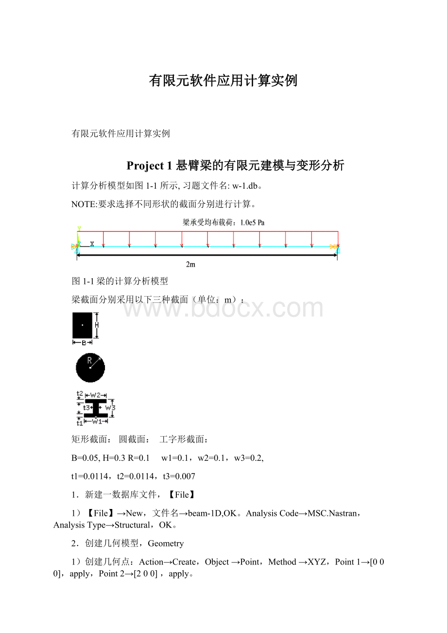
Project1悬臂梁的有限元建模与变形分析
计算分析模型如图1-1所示,习题文件名:
w-1.db。
NOTE:
要求选择不同形状的截面分别进行计算。
图1-1梁的计算分析模型
梁截面分别采用以下三种截面(单位:
m):
矩形截面:
圆截面:
工字形截面:
B=0.05,H=0.3R=0.1w1=0.1,w2=0.1,w3=0.2,
t1=0.0114,t2=0.0114,t3=0.007
1.新建一数据库文件,【File】
1)【File】→New,文件名→beam-1D,OK。
AnalysisCode→MSC.Nastran,AnalysisType→Structural,OK。
2.创建几何模型,Geometry
1)创建几何点:
Action→Create,Object→Point,Method→XYZ,Point1→[000],apply,Point2→[200],apply。
2)创建曲线:
Action→Create,Object→Curve,Method→Point,Option→2Point,Curve1,StartingPointList→point1,EndingPointList→point2,apply。
3.划分有限元网格,Elements
1)建立网格种子:
Action→Create,Object→MeshSeed,Type→Uniform,NumberofElement,Number→10,AutoExecute,CurveList→Curve1。
2)划分网格:
Action→Create,Object→Mesh,Type→Curve,Topology→Bar2,CurveList→Curve1,apply。
4.施加边界条件,Loads/BCs
1)施加固定约束:
Action→Create,Object→Displacement,Type→Nodal,NewSetName→dis1,InputData,Translations→<000>,Rotations→<000>,OK,SelectApplicationRegion,FEM,SelectNodes→Node1,Add,OK,apply。
2)施加均布载荷:
Action→Create,Object→CIDDistributedLoad,Type→ElementUniform,NewSetName→CID1,TargetElementTypet→1D,InputData,DistrForce→<0-1.0e50>,OK,SelectApplicationRegion,FEM,Select1DElements→Elm1:
40,OK,apply。
5.定义材料属性,Materials
定义材料:
Action→Create,Object→Isotropic,Method→ManualInput,MaterialName→steel,InputData,ConstitutiveModel→LinearElastic,ElasticModulus→2.1e11,PoissonRatio→0.3,OK,apply。
6.定义单元属性,Proper(注:
三种截面分别执行步骤7,8)
1.1矩形截面:
定义单元属性:
Action→Create,Object→1D,Type→Beam,PropertySetName→pro1,Option(s)→GeneralSection、StandardFormulation,InputProperties,单击CreateSection,Action→Create,Object→StandardShape,Method→NASTRANStandard,SectionName→rect,单击【<】,选择
,W→0.05,H→0.3,OK,MaterialName→Steel(在MaterialPropertySets中选择),BarOrientation→<0,1,0>,OK,SelectMembers→Curve1,Add,apply。
7,8。
1.2圆截面:
定义单元属性:
Action→Create,Object→1D,Type→Beam,PropertySetName→pro2,Option(s)→GeneralSection、StandardFormulation,InputProperties,单击CreateSection,Action→Create,Object→StandardShape,Method→NASTRANStandard,SectionName→cir,单击【<】,选择
,R→0.1,OK,MaterialName→Steel(在MaterialPropertySets中选择),BarOrientation→<0,0,1>,OK,SelectMembers→Curve1,Add,apply。
7,8。
1.3工字形截面:
定义单元属性:
Action→Create,Object→1D,Type→Beam,PropertySetName→pro3,Option(s)→GeneralSection、StandardFormulation,InputProperties,单击CreateSection,Action→Create,Object→StandardShape,Method→NASTRANStandard,SectionName→cir,单击【<】,选择
,H→0.2,w1→0.1,w2→0.1,t→0.007,t1→0.0114,t2→0.0114,OK,MaterialName→Steel(在MaterialPropertySets中选择),BarOrientation→<0,0,1>,OK,SelectMembers→Curve1,Add,apply。
7,8。
7.进行分析,Analysis
1)进行分析:
Action→Analyze,Object→EntireModel,Type→AnalysisDeck,JobName→beam-1D,单击SolutionType,SolutionType→LINEARSTATIC,OK,apply。
打开NASTRAN,选择beam-1D.bdf,Run。
此时,Patran会将模型提交Nastran运算,会弹出一个DOS形式的窗口,显示Nastran的运行情况,运算完成之后,计算机的扬声器会有提示音,同时,状态显示窗口关闭。
2)读入分析结果:
Action→AccessResults,Object→AttachXDB,Method→ResultEntities,SelectResultFile,文件名→beam-1D.xdb,OK,apply。
这一步骤,是将Nastran的分析结果读入到Patran中来,这样才可以进行后处理。
8.后处理,Results
1)显示应力云纹图:
Action→Create,Object→QuickPlot,SelectResultCases→DefaultStaticSubcase,SelectFringeResult→DisplacementsTranslational,Bending,Quantity→vonMises,apply。
此时,平板模型的vonMises弯曲应力云纹图就显示出来,如图1-1所示。
图1-1
2)显示位移云纹图:
Action→Create,Object→QuickPlot,SelectResultCases→DefaultStaticSubcase,SelectDeformationResult→DisplacementsTranslational,Quantity→Magnitude,apply。
此时,平板模型的位移云纹图就显示出来,如图1-2所示。
图1-2
Project2悬臂梁的有限元建模与变形分析(2D)
分析模型采用Project1中的矩形梁,由于其厚度B远远小于其高度H和长度,故可认为是一平面应力问题。
1.新建一数据库文件,【File】
1)【File】→New,文件名→beam-2D,OK。
AnalysisCode→MSC.Nastran,AnalysisType→Structural,OK。
2.创建几何模型,Geometry
1)创建几何点:
Action→Create,Object→Point,Method→XYZ,Point1→[000],apply,Point2→[200],Point3→[00.30],apply,Point4→[20.30],apply。
2)创建曲线:
Action→Create,Object→Curve,Method→Point,Option→2Point,Curve1,StartingPointList→point1,EndingPointList→point2,apply,Curve2,StartingPointList→point3,EndingPointList→point4,apply。
3)创建曲面:
Action→Create,Object→Surface,Method→Curve,Option→2Curve,Surface1,StartingCurveList→Curve1,EndingCurveList→Curve2,apply。
3.划分有限元网格,Elements
1)建立网格种子:
Action→Create,Object→MeshSeed,Type→Uniform,NumberofElement,Number→10,AutoExecute,CurveList→Curve1,apply,NumberofElement,Number→4,AutoExecute,CurveList→Surface1.3,apply。
2)划分网格:
Action→Create,Object→Mesh,Type→Surface,ElemShape→Quad,Mesher→Isomesh,Topology→Quad8,SurfaceList→Surface1,apply。
4.施加边界条件,Loads/BCs
1)施加固定约束:
Action→Create,Object→Displacement,Type→Nodal,NewSetName→dis2,InputData,Translations→<000>,Rotations→<000>,OK,SelectApplicationRegion,Geometry,SelectSurfacesorEdges→Surface1.2,Add,OK,apply。
2)施加均布载荷:
Action→Create,Object→CIDDistributedLoad,Type→ElementUniform,NewSetName→CID2,TargetElementTypet→2D,InputData,SurfDistrForce→<0-1.0e50>,OK,SelectApplicationRegion,Geometry,SelectSurfacesorEdges→Surface1.1,Add,OK,apply。
5.定义材料属性,Materials
定义材料:
Action→Create,Object→Isotropic,Method→ManualInput,MaterialName→steel,InputData,ConstitutiveModel→LinearElastic,ElasticModulus→2.1e11,PoissonRatio→0.3,OK,apply。
6.定义单元属性,Proper
1)定义单元属性:
Action→Create,Object→2D,Type→shell,PropertySetName→pro,Option(s)→Homogeneous、StandardFormulation,InputProperties,MaterialName→Steel(在MaterialPropertySets中选择),Thickness→0.05,OK,SelectMembers→Surface1,Add,apply。
7.进行分析,Analysis
1)进行分析:
Action→Analyze,Object→EntireModel,Type→AnalysisDeck,JobName→beam-2D,单击SolutionType,SolutionType→LINEARSTATIC,OK,apply。
打开NASTRAN,选择beam-2D.bdf,Run。
此时,Patran会将模型提交Nastran运算,会弹出一个DOS形式的窗口,显示Nastran的运行情况,运算完成之后,计算机的扬声器会有提示音,同时,状态显示窗口关闭。
2)读入分析结果:
Action→AccessResults,Object→AttachXDB,Method→ResultEntities,SelectResultFile,文件名→beam-2D.xdb,OK,apply。
这一步骤,是将Nastran的分析结果读入到Patran中来,这样才可以进行后处理。
8.后处理,Results
1)显示应力云纹图:
Action→Create,Object→QuickPlot,SelectResultCases→DefaultStaticSubcase,SelectFringeResult→StressTensor,Quantity→vonMises,apply。
此时,平板模型的vonMises弯曲应力云纹图就显示出来,如图2-1所示。
图2-1
2)显示位移变形图:
Action→Create,Object→QuickPlot,SelectResultCases→DefaultStaticSubcase,SelectDeformationResult→DisplacementsTranslational,Quantity→Magnitude,apply。
此时,平板模型的位移云纹图就显示出来,如图2-2所示。
图2-2
Project3悬臂梁的有限元建模与变形分析(2D/3D)
分析模型采用Project1中的矩形梁,这里采用三维有限元模型进行分析。
1.新建一数据库文件,【File】
1)【File】→New,文件名→beam-3D,OK。
AnalysisCode→MSC.Nastran,AnalysisType→Structural,OK。
2.创建几何模型,Geometry
1)创建几何点:
Action→Create,Object→Point,Method→XYZ,Point1→[000],apply,Point2→[200],Point3→[00.30],apply,Point4→[20.30],apply。
2)创建曲线:
Action→Create,Object→Curve,Method→Point,Option→2Point,Curve1,StartingPointList→point1,EndingPointList→point2,apply,Curve2,StartingPointList→point3,EndingPointList→point4,apply。
3)创建曲面:
Action→Create,Object→Surface,Method→Curve,Option→2Curve,Surface1,StartingCurveList→Curve1,EndingCurveList→Curve2,apply。
4)创建实体:
Action→Create,Object→Solid,Option→Extrude,SolidType
,TranslationVector→<000.05>,SurfaceList→Surface1,apply。
3.划分有限元网格,Elements
1)建立网格种子:
Action→Create,Object→MeshSeed,Type→Uniform,NumberofElement,Number→10,AutoExecute,CurveList→Solid1.4.3,apply,NumberofElement,Number→5,AutoExecute,CurveList→Solid1.1.2,apply,NumberofElement,Number→2,AutoExecute,CurveList→Solid1.1.3,apply。
2)划分网格:
Action→Create,Object→Mesh,Type→Solid,ElemShape→Hex,Mesher→Isomesh,Topology→Hex8,SolidList→Solid1,apply。
4.施加边界条件,Loads/BCs
1)施加固定约束:
Action→Create,Object→Displacement,Type→Nodal,NewSetName→dis3,InputData,Translations→<000>,Rotations→<000>,OK,SelectApplicationRegion,FEM,Select→Node1:
452:
41,Add,OK,apply。
2)施加均布载荷:
Action→Create,Object→CIDDistributedLoad,Type→ElementUniform,NewSetName→CID3,TargetElementTypet→3D,InputData,DistrForce→<0-1.0e50>,OK,SelectApplicationRegion,Geometry,SelectSolidFace→Solid1.4,Add,OK,apply。
5.定义材料属性,Materials
定义材料:
Action→Create,Object→Isotropic,Method→ManualInput,MaterialName→steel,InputData,ConstitutiveModel→LinearElastic,ElasticModulus→2.1e11,PoissonRatio→0.3,OK,apply。
6.定义单元属性,Proper
定义单元属性:
Action→Create,Object→3D,Type→Solid,PropertySetName→pro,Option(s)→Homogeneous、StandardFormulation,InputProperties,MaterialName→m1(在MaterialPropertySets中选择),OK,SelectMembers→Solid1,Add,apply。
7.进行分析,Analysis
1)进行分析:
Action→Analyze,Object→EntireModel,Type→AnalysisDeck,JobName→beam-3D,单击SolutionType,SolutionType→LINEARSTATIC,OK,apply。
打开NASTRAN,选择beam-3D.bdf,Run。
此时,Patran会将模型提交Nastran运算,会弹出一个DOS形式的窗口,显示Nastran的运行情况,运算完成之后,计算机的扬声器会有提示音,同时,状态显示窗口关闭。
2)读入分析结果:
Action→AccessResults,Object→AttachXDB,Method→ResultEntities,SelectResultFile,文件名→beam-3D.xdb,OK,apply。
这一步骤,是将Nastran的分析结果读入到Patran中来,这样才可以进行后处理。
8.后处理,Results
1)显示应力云纹图:
Action→Create,Object→QuickPlot,SelectResultCases→DefaultStaticSubcase,SelectFringeResult→StressTensor,Quantity→vonMises,apply。
此时,平板模型的vonMises弯曲应力云纹图就显示出来,如图3-1所示。
图3-1
2)显示位移变形图:
Action→Create,Object→QuickPlot,SelectResultCases→DefaultStaticSubcase,SelectDeformationResult→DisplacementsTranslational,Quantity→Magnitude,apply。
此时,平板模型的位移云纹图就显示出来,如图3-2所示。
图3-2
 升级会员
升级会员 