AAN100操作说明书英文.docx
《AAN100操作说明书英文.docx》由会员分享,可在线阅读,更多相关《AAN100操作说明书英文.docx(25页珍藏版)》请在冰豆网上搜索。
AAN100操作说明书英文
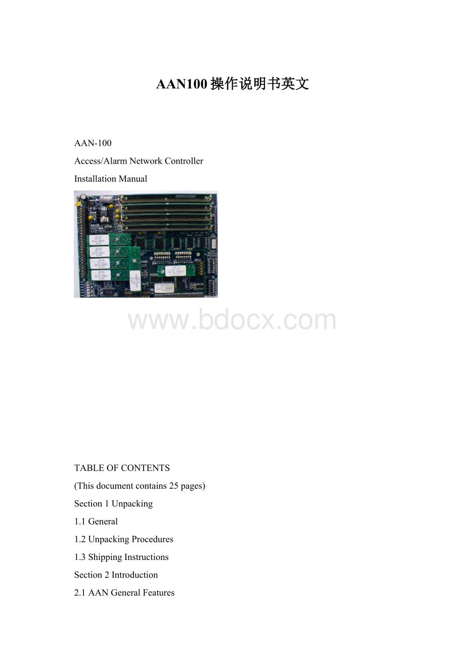
AAN-100
Access/AlarmNetworkController
InstallationManual
TABLEOFCONTENTS
(Thisdocumentcontains25pages)
Section1Unpacking
1.1General
1.2UnpackingProcedures
1.3ShippingInstructions
Section2Introduction
2.1AANGeneralFeatures
2.2MemoryExpansionOption
2.3CommunicationPorts
2.3.1ANI-1NetworkInterfaceModule
2.4PowerInputProtection
Section3Installation
3.1MountingtheAAN
3.2PowerFaultandCabinetTamperWiring
3.3CommunicationwiththeHost
3.3.1LocalPrintout
3.4CommunicationwithSlaveDevices
3.4.1LocalPrintout
3.5PowerWiring
3.6PowerONIndicator
3.7InstallingMemoryBackupBatteries
3.8MemoryExpansionModuleInstallation
3.9InstallatingaSecondANIModule
3.10InstallationVerification
3.11Repair/ReplacementofFailedUnits
Section4Configuration
4.1AAN-100DIPSwitches
4.2ASI-1DIPSwitches
Section5Specifications
FigureIllustrations
139EnclosurewithbasicAANandPowerSupply
140PCBoardLayout
141PowerFault/CabinetTamperWiring
142AANtoSlaveDevicesCommunicationWiring(RS-485)
143AANtoSlaveDevicesCommunicationWiring(RS-232/Modem)
144AANtoHostCommunicationWiring
145LocalPrinterConnection
146PowerSupplyWiring
147UPSWiring
148InstallingMemoryBackupBatteries
149ANI-1Installation
150OptionalPlug-inModuleDimensions
SAFETYPRECAUTIONS
Anumberofsafetyprecautionsappearinvariousparagraphsonthefollowingpages.Asummaryofthoseprecautionsarerepeatedbelowforemphasis:
CAUTION
Ifanydamagetotheshipmentisnoticed,aclaimmustbefiledwiththecommercialcarrierresponsible.
CAUTION
Severalimportantproceduresshouldbefollowedtopreventelectro-staticdischarge(ESD)damagetosensitiveCMOSintegratedcircuitsandmodules.
•Alltransportofelectroniccomponents,includingcompletedreaderassemblies,shouldbeinstaticshieldpackagingandcontainers.
•HandleallESDsensitivecomponents,atanapprovedstaticcontrolledworkstation.Theseworkstationsconsistofadeskmat,floormatandaESDwriststrap.Workstationsareavailablefromvariousvendorsincludingthe3Mcompany.
WARNING
Powershouldnotbeappliedtothesystemuntilaftertheinstallationhasbeencompleted.Ifthisprecautionisnotobserved,personalinjuryordeathcouldoccur,andtheequipmentcouldbedamagedbeyondrepair.
WARNING
Verifythattheexternalcircuitbreakerwhichsuppliespowertothedevicepowersupplyisturnedoffpriortoinstallation.
WARNING
Verifythattheoutputvoltageofthepowersupplyiswithinspecificationspriortoconnectiontothedevice.
WARNING
Thisequipmentgenerates,uses,andcanradiateradiofrequencyenergy.Ifnotinstalledandusedinaccordancewiththeinstallationandoperatingmanuals,itmaycauseinterferencetoradiocommunications.
Operationofthisequipmentinaresidentialareamaycauseinterference.Inthiscase,theuserwillberequiredtotakenecessarymeasurestocorrecttheinterference(Thiswarningisprovidedasrequiredbyfederallaw).
Section1Unpacking
1.1General
Thissectionprovidesastepbystepprocedureforunpacking,inspectingandreturningequipment.
1.2UnpackingProcedure
CAUTION
Ifanydamagetotheshipmentisnoticedbeforeunpacking,aclaimmustbefiledwiththecommercialcarrier.
Allcontainersshouldbeopenedandunpackedcarefullyinordertopreventdamagetothecontents.
Thefollowingstepsareusedtounpackequipmentinpreparationforinstallation:
1.Openthecontainerandremovetheunit(s)andallpackingmaterial.Retainthecontainerandallpackingmaterials.Theymaybeusedagainforre-shipmentoftheequipment,ifneeded.
2.Inspectthecontentsforshortage.Ifitemsaremissing,contacttheorderentrydepartment.
3.Visuallycheckcontents.Ifdamageisdiscovered,performthefollowing:
a.Ifdamagewascausedbyshipping,claimmustbefiledwiththecommercialcarrier.
b.Ifanyotherdefectisapparent,callforreturnauthorization.
1.3ShippingInstructions
Thefollowingstepsareusedtoshipanyequipment:
1.Contactthecustomerservicedepartmentpriortoreturningequipment.
Whenyoucall,pleasehaveavailable:
a.Adescriptionoftheproblemorreasonyouarereturningtheequipment.
b.Youroriginalpurchaseordernumber,invoicenumber,andiftheunitisstillunderwarranty.
c.Anewpurchaseordernumberiftheunitisnotunderwarranty
2.ObtaintheReturnAuthorizationNumber(RMA)fromthecustomerservicedepartment.
3.ShowtheRMAnumberonallpackagesshipped.PackageswhicharenotmarkedwithanRMAnumberwillberefusedatthefactoryandreturnedtoyou-COD.
4.Carefullypacktheequipmentandpriortoshipment.
Section2Introduction
2.1AANGeneralFeatures
TheAAN-100alarm/accessnetworkcontrollerisamodularsystemthatprovidesfulldistributedprocessingforaccesscontrol,alarmreportingandremotecontroloperationinnetworkapplications.
TheAANsystemprovides4plug-inmemorymoduleSIMMsockets,forupto8MbytesofRAM,upto2ANI-1Ethernetmodules(10BASE-TandAUIinterfaceoneach),andupto6ASM-23,(RS-232)orASM-48,
(RS-485)deviceportandhostportdrivermodules.
TheAANprovidesthefollowinghardwarefeatures:
•HighspeedCMOS32bitmicroprocessor
•6serialports(4deviceportsupto9600baud,2hostportsupto57.6Kbaud)
•Batteryback-upofaccessdatabaseandevents
•DIPswitchesforconfigurationoptions
•StatusLEDsforoperationanddiagnostics
•RS-232/RS-485/Ethernetcommunication
•Uniqueaddress.Upto8AAN-100sonasinglecommunicationline(RS-485).
2.2MemoryExpansionOptions
ThestandardAANconfigurationprovides1MbyteofhighspeedstaticRAMforcardholderandeventstorage.Optionalplug-inmemoryexpansionmodulescanprovide,upto8Mbytes(using42MbyteAME-20modules)forexpandedcardholderandeventstorage.
NOTE:
Eventstoragereducestheamountofmemorythatcanusedtostorethedatabase.Thehostsoftwareconfiguresthenumberofcardholdersthatthedatabasewillholdandtherestofthespaceisusedforeventstorage.Eacheventstoreduses12bytespereventandaminimumof100eventsisalwaysreserved.Databasestorageoverheadusesabout10percentoftheavailablememory.
Amountofmemoryforcardholderdatabaseandeventstorage:
1MB-839,577bytes
2MB-1,783,296bytes
4MB-3,670,732bytes
8MB-7,445,606bytes
2.3CommunicationPorts
TheAANhas6highspeedserialcommunicationports.Ports3-6arenormallyusedtocommunicatewithdevicessuchascardreaders,alarmpanelsandstatuspanels.Theremainingtwoports(1and2)maybeusedasadualpathtothehostwhenemployingtheANI-I,NetworkInterfacemodule,asasingleporttothehostwithalocalprintout/displayofeventactivityontheotherport,orasadualserialpathtothehost,whenusingtheASI-1,SerialInterfacemodule.
Alldeviceports(1-6)canbeconfiguredforeitherRS-232orRS-485communicationusingoptionalplug-indrivermodules:
ASM-23(430-131)forRS-232,orASM-48(430-132)forRS-485(SeeFigure140).
Port1oftheASI-1hasthefullcomplementofsignalsfordialmodemcommunication(SeeFigure144).
2.3.1ANI-1NetworkInterfaceModule
Upto2ANI-1modulesaresupportedbytheAAN.TheANIprovidesanAUIconnector(DB15)anda10BASE-Tconnector(RJ-45)forconnectiontoanyLANcablemediumwithasimple,plug-ininstallation.
TheANIhas3diagnosticsLEDs:
POL(polarity)isayellowLEDthatilluminateswhenthepolarityoftheincomingdataisreversed.ACT(activity)isagreenLEDindicatingthatcommandsfromthehostarebeingreceived.LINKisagreenLEDthatilluminateswhenaLINKpulsefromthehostisreceived.
TheANIhas2jumpers,JP1andJP2.Inasystemwhichuses2ANImodules,JP1mustberemovedfromonemoduletoidentifytheirsystemaddresses.JP2mustberemovedinsystemswhichareusingAUI.
2.4PowerInputProtection
TheAAN-100PCBassemblyisprotectedfromover-currentandover-voltagebyon-boardcircuity.
Whenanover-currentconditionoccurs,solid-statefusestriptoprotecttheassembly.Inmanycases,thesolid-statefusesautomaticallyresetwhennormalcurrentresumes,otherwise,thecircuitcurrentmustbeinterruptedtoresetthedevices.
EachcommunicationmoduleisprotectedfromvoltagesurgesandESDbystate-of-the-artsemiconductortransientvoltagesuppressors.
Section3Installation
InstallationoftheAAN-100requiresthefollowingsteps:
•Plug-inoptionalmodules
•MounttheAANassembly
•Wirethepowerfault/cabinettamper
•WiretheRS-485/RS-232ornetworkcommunicationlinktothehost
•Wiretheslavedevices
•WirepowertotheAAN
•ConfiguretheAAN
•Verifytheinstallationandchecksystemfunctions
•Installthememoryback-upbatteries
3.1MountingModules
3.2MountingtheAAN
TheAAN-100motherboard(withoptions)isinstalledinautilitycabinet/enclosure.ThePCboardhas4holesformounting(SeeFigure139).
3.3PowerFaultandCabinetTamperWiring
WiresareconnectedasshowninFigure141.
3.4CommunicationwiththeHost
Port1istheprimarycommunicationpathtothehost.WhenusingtheASI-1DUART,configurePort1usingDIPswitchSW1ontheASI-1,asdescribedinSection4.2.
SelectRS-232orRS-485,plugginginthedesireddriver,asshowninFigure141.IfusingRS-485,installRS-485terminators(ATM-48,P/N470-030)atbothends.ObservethegeneralguidelinesforRS-485communication.
WirethecommunicationlinktothehostasshowninFigure144.
NOTE:
Port2maybeconfiguredasanalternat
 升级会员
升级会员 