H3CNE 大综合实验 覆盖所有的H3CNE课程.docx
《H3CNE 大综合实验 覆盖所有的H3CNE课程.docx》由会员分享,可在线阅读,更多相关《H3CNE 大综合实验 覆盖所有的H3CNE课程.docx(27页珍藏版)》请在冰豆网上搜索。
H3CNE大综合实验覆盖所有的H3CNE课程
组名:
SUNRISE
小组成员:
孙弋伦,钟良引,吴淑敏,陈师伟,韩纬光
一.实验名称:
OSPF路由多区域
二.实验需求及应用环境:
需求及背景描述
公司分布在3个不同的城市,分别在北京,上海,海南,全网使用OSPF互联
三.网络拓朴:
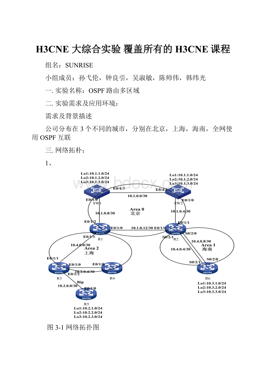
1、
图3-1网络拓扑图
2、IP分配表
我们使用10.0.0.0/8网段的的私网地址来进行规划。
Ip地址的9-16位代表地区。
1代表北京例如:
10.1.0.0/24
2代表上海例如:
10.2.0.0/24
3代表海南例如:
10.3.0.0/24
4代表链路地址例如:
10.4.0.0/30
Ip地址的17-24位代业务网段。
0代表接口ip地址例如:
10.0.0.0/30
1代表财务处ip地址例如:
10.0.1.0/24
2代表销售部ip地址例如:
10.0.2.0/24
3代表网络中心ip地址例如:
10.0.3.0/24
表3-1北京地区ip地址规划
北京
配置名称
IP地址
子网掩码
默认网关
财务处
10.1.1.0
255.255.255.0
10.1.1.1
销售部
10.1.2.0
255.255.255.0
10.1.2.1
网络中心
10.1.3.0
255.255.255.0
10.1.3.1
接口ip地址
10.1.0.0
255.255.255.0
\
表3-1上海地区ip地址规划
上海
配置名称
IP地址
子网掩码
默认网关
财务处
10.2.1.0
255.255.255.0
10.2.1.1
销售部
10.2.2.0
255.255.255.0
10.2.2.1
网络中心
10.2.3.0
255.255.255.0
10.2.3.1
接口ip地址
10.2.0.0
255.255.255.0
\
表3-1海南地区ip地址规划
上海
配置名称
IP地址
子网掩码
默认网关
财务处
10.3.1.0
255.255.255.0
10.3.1.1
销售部
10.3.2.0
255.255.255.0
10.3.2.1
网络中心
10.3.3.0
255.255.255.0
10.3.3.1
接口ip地址
10.3.0.0
255.255.255.0
\
3、交换机IP配置
表2-2交换机IP配置
设备名称
设备接口
IP地址
SW1
Vlan1
10.1.0.0/30
Lo1
10.1.1.1/24
Lo2
10.1.2.1/24
Lo3
10.1.3.1/24
E0/4/3
/
E0/1/0
10.1.0.8/30
Sw2
Vlan1
10.1.0.0/30
Lo1
10.1.1.2/24
Lo2
10.1.2.2/24
Lo3
10.1.3.2/24
E0/1/0
10.1.0.4/30
E0/4/3
/
4、路由器IP配置
表2-3路由器IP配置
设备名称
设备接口
IP地址
R1
E0/1/0
10.1.0.12/30
E0/1/1
10.4.0.0/30
E0/1/2
10.1.0.8/30
R2
E0/1/0
10.1.0.12/30
E0/1/1
10.1.0.4/30
S0/2/0
10.4.0.8/30
S0/2/1
10.4.0.4/30
R3
E0/1/0
10.2.0.4/30
E0/1/1
10.4.0.0/30
E0/1/2
10.2.0.0/30
R4
E0/1/0
10.2.0.4/30
R5
E0/1/0
10.2.0.0/30
Lo1
10.2.1.1/24
Lo2
10.2.2.1/24
Lo3
10.2.3.1/24
R6
S0/2/0
10.4.0.8/30
S0/2/1
10.4.0.4/30
Lo1
10.3.1.1/24
Lo2
10.3.2.1/24
Lo3
10.3.3.1/24
四.预期要达到的实验结果:
(一)、需求分析
1、工程化的ip地址分配
2、实现全网互通。
3、OSPF多区域的划分
4、将Area1区域设置成Stub区域。
5、通过修改cost值实现链路的备份。
6、业务端口设置为禁默端口。
7、远程接入的设备需要做认证。
8、实现rip的路由汇总。
9、实现OSPF的区域路由的汇总。
10、路由重发布
地域图如下
图4-1公司地理位置分布图
五.配置思路步骤:
(工程配置思想)
1、接口的配置
表5-1设备接口配置
SW1
interfacee0/1/0
ipaddress10.1.0.930
interfacevlan1
ipaddress10.1.0.130
undoshutdown
interfacelo1
ipaddress10.1.1.124
interfacelo2
ipaddress10.1.2.124
interfacelo3
ipaddress10.1.3.124
SW2
interfacee0/1/0
ipaddress10.1.0.530
interfacevlan1
ipaddress10.1.0.230
undoshutdown
interfacelo1
ipaddress10.1.1.224
interfacelo2
ipaddress10.1.2.224
interfacelo3
ipaddress10.1.3.224
R1
interfacee0/1/2
ipaddress10.1.0.1030
interfacee0/1/0
ipaddress10.1.0.1330
interfacee0/1/1
ipaddress10.4.0.130
R2
interfacee0/1/0
ipaddress10.1.0.1430
interfacee0/1/1
ipaddress10.1.0.630
interfaces0/2/0
ipaddress10.4.0.930
interfaces0/2/1
ipaddress10.4.0.530
R3
interfacee0/1/1
ipaddress10.4.0.230
interfacee0/1/0
ipaddress10.2.0.530
interfacee0/1/2
ipaddress10.2.0.130
R4
interfacee0/1/0
ipaddress10.2.0.630
R5
interfacee0/1/0
ipaddress10.2.0.230
interfacelo1
ipaddress10.2.1.124
interfacelo2
ipaddress10.2.2.124
interfacelo3
ipaddress10.2.3.124
R6
interfaces0/2/0
ipaddress10.4.0.1030
interfaces0/2/1
ipaddress10.4.0.630
interfacelo1
ipaddress10.3.1.124
interfacelo2
ipaddress10.3.2.124
interfacelo3
ipaddress10.3.3.124
2、OSPF技术
表5-2OSPF技术实现
SW1
routerid11.11.11.11
ospf
area0
network10.1.0.80.0.0.3
network10.1.0.00.0.0.3
network10.1.1.00.0.0.255
network10.1.2.00.0.0.255
network10.1.3.00.0.0.255
SW2
routerid22.22.22.22
ospf
area0
network10.1.0.40.0.0.3
network10.1.0.00.0.0.3
network10.1.1.00.0.0.255
network10.1.2.00.0.0.255
network10.1.3.00.0.0.255
R1
routerid1.1.1.1
ospf
area0
network10.1.0.80.0.0.3
network10.1.0.120.0.0.3
area2
network10.4.0.00.0.0.3
R2
routerid2.2.2.2
ospf
area0
network10.1.0.40.0.0.3
network10.1.0.120.0.0.3
area1
network10.4.0.40.0.0.3
network10.4.0.80.0.0.3
R3
routerid3.3.3.3
ospf
area2
network10.4.0.00.0.0.3
network10.2.0.40.0.0.3
R4
routerid4.4.4.4
ospf
area2
network10.2.0.40.0.0.3
R6
routerid5.5.5.5
ospf
area1
network10.4.0.40.0.0.3
network10.4.0.80.0.0.3
3、RIP技术
表5-3RIP技术的实现
R3
rip
version2
undosummary
network10.2.0.0
R4
rip
version2
undosummary
network10.2.0.0
4、路由表重发布
表5-4路由重发布
R3
rip
import-routeospfcost5//将OSPF的路由表放进RIP,开销为5
ospf
import-routeripcost10//将RIP的路由表放进OSPF,开销为10
5、OSPF的接入认证
表5-5OSPF的接入认证
R1
ospf
area2
authentication-modesimple
interfacee0/1/1
ospfauthentication-modesimpleplainbjtosh
R3
ospf
area2
authentication-modesimple
interfacee0/1/1
ospfauthentication-modesimpleplainbjtosh
interfacee0/1/0
ospfauthentication-modesimpleplainshtosh
R4
ospf
area2
authentication-modesimple
interfacee0/1/0
ospfauthentication-modesimpleplainshtosh
R2
ospf
area1
authentication-modesimple
interfaces0/2/0
ospfauthentication-modesimpleplainbjtohn
interfaces0/2/1
ospfauthentication-modesimpleplainbjtohn
R6
ospf
area1
authentication-modesimple
interfaces0/2/0
ospfauthentication-modesimpleplainbjtohn
interfaces0/2/1
ospfauthentication-modesimpleplainbjtohn
6、静默端口
表5-6静默端口的设置
SW1SW2R6
ospf
silent-interfacelo1
silent-interfacelo2
silent-interfacelo3
R5
rip
silent-interfacelo1
silent-interfacelo2
silent-interfacelo3
7、链路备份
表5-7修改cost达到链路备份
R2R6
interfaces0/2/0
ospfcost2000
8、Stub区域
表5-8Stub区域的设置
R2R6
ospf
area1
stub
9、RIP路由汇聚
表5-9RIP的路由汇聚
R5
interfacee0/1/0
ripsummary-address10.2.0.022
R3
interfacee0/1/2
ripsummary-address10.0.0.013
10、OSPF区域的路由汇聚
表5-10OSPF区域1的路由汇聚
R2
ospf
area1
abr-summary10.3.0.022
表5-11OSPF区域0的路由汇聚
R1R2
ospf
area0
abr-summary10.1.0.022
六.实验调试过程:
1、
图6-1:
R1路由表条目
链路备份前
备份后
2、
Stub区域后效果
Rip汇聚前
Rip汇聚后
区域1聚合前
区域1聚合后
区域0的路由汇总前
区域0路由汇总后
Rip汇总前
Rip捆绑后
4、
图6-5链路捆绑
5、
图6-6SW1MSTP实例0和实例1根桥
6、
图6-7SW1MSTP实例2根桥
7、
图6-8DHCP地址池范围
8、
图6-9FTPserver的搭建
七.实验调试结果:
1、
图7-1非网络中心不能登录
2、
图7-42Console密码认证
3、
图7-3测试分公司的连通性,
4、
图7-4到两个部门的连通性
5、
图7-5非网络中心telnet测试
6、
图7-6部门到外网的连通性
八.实验总结:
1、通过实验串通所有学过的知识点,懂得怎样融合知识点到一个项目中;
2、根据分析客户的需求进行技术上的分析,然后就可以清晰的实现项目;
3、实验运用到了:
vlan、telnet、ftp、ppp、acl、nat、dhcp、mstp、rip、ospf、静态路由、链路捆绑技术、路由重发布,静默端口、rip的接入认证、svi、trunk;
4、实验中我们做了路由重发布,为了将rip的路由表发布到ospf中里;
5、实验过程中进行捆绑时已显示配置成功,但验证过程没有成功,后来通过几番的检查才得以解决;
6、做这个实验虽然有点辛苦,但体味到一个组团结的力量,也体味到做项目的一点点艰辛;
 升级会员
升级会员 