zemax非顺序系设计教程.docx
《zemax非顺序系设计教程.docx》由会员分享,可在线阅读,更多相关《zemax非顺序系设计教程.docx(27页珍藏版)》请在冰豆网上搜索。

zemax非顺序系设计教程
如何创建一个简单的非顺序系统
SettingupBasicSystemProperties建立基本系统属性
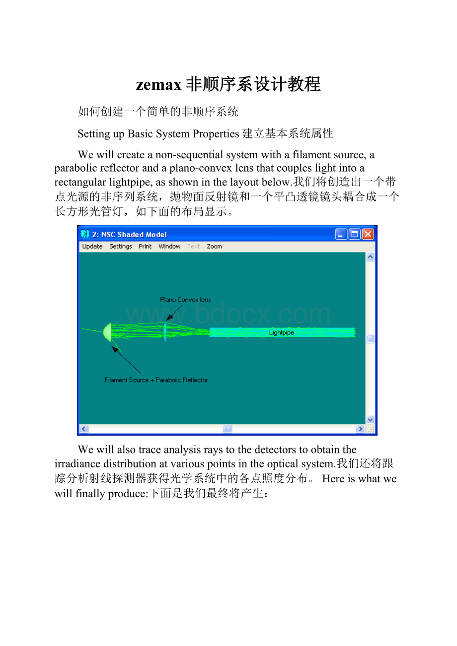
Wewillcreateanon-sequentialsystemwitha filamentsource,aparabolicreflectorandaplano-convexlensthatcoupleslightintoarectangularlightpipe,asshowninthe layoutbelow.我们将创造出一个带点光源的非序列系统,抛物面反射镜和一个平凸透镜镜头耦合成一个长方形光管灯,如下面的布局显示。
Wewillalsotraceanalysisraystothedetectorstoobtaintheirradiancedistributionatvariouspointsintheopticalsystem.我们还将跟踪分析射线探测器获得光学系统中的各点照度分布。
Hereiswhatwewillfinallyproduce:
下面是我们最终将产生:
IfZEMAXisnotrunning,pleasestartitnow.如果ZEMAX软件没有运行,启动它。
Bydefault,ZEMAXstartsinsequential/mixedmode.默认情况下,ZEMAX软件启动顺序/混合模式。
Toswitchtopurenon-sequentialmode,openZEMAXandclickFile>NonSequentialMode.要切换到纯非连续模式,运行ZEMAX软件,然后点击文件“>非序列模式。
Onceinpurenon-sequentialmode,thewindowtitlebaroftheeditorwilldisplaytheNon-SequentialComponentEditorinsteadoftheLensDataEditorwheninsequentialmode.一旦纯非连续模式,在编辑器窗口的标题栏将显示非连续组件编辑器而不是在连续模式时只用于连续或混合模式系统的镜头数据编辑。
TheLensDataEditor isused only insequentialormixed-modesystems.
Forthisexercise,wewillsetthesystemwavelength,specifiedunderSystem>Wavelengths,to0.587µm.对于本练习,我们会设置系统波长,点击系统>波长,指定波长0.587微米。
WewillalsosettheunitsunderSystem>GeneralUnittabasfollows(default).我们还将在系统设置单位,System>General/Unittab“一般组标签如下(默认)(default).。
InadditiontoradiometricirradianceunitsuchasWatt.cm-2,youcanspecifyphotometricandenergyunitssuchaslumen.cm-2orjoule.cm-2.除除辐射辐照装置单位如Watt.cm-2外,您可以指定光度和能源单位,如lumen.cm-2或joule.cm-2。
Wewillchoosethedefaultradiometricunitsforthisexercise.我们将选择默认为这项工作辐射单位。
创建反射
Insertafewlinesinthenon-sequentialcomponenteditorbypressingthe“Insert”keyonyourkeyboard.按键盘上的“插入”(insert)插入几行非序列编辑器。
Inthefirstpartofthedesign,wewillcreateafilamentsourcecollimatedbyaparabolicreflector.在设计的第一部分,我们将创建一个由抛物面反射镜准直的线光源。
Wewillthenplaceadetectorobjectatsomedistance+Zandlookattheirradiancedistributionon adetector.然后,我们将在+Z上放置探测器对象和看光照在探测器上的分布。
建立第一个对象通过抛物面反射镜。
在编辑器对象1列“对象类型”(Objecttype)双击(右击一下)下,打开Makethefirstobjectaparabolicreflectorbydoubleclicking(leftclicking)onthe“Objecttype”columnofObject1intheeditorandopeningtheObjectPropertywindow.,打开对象的属性窗口。
UndertheTypetabsettheTypetoStandardSurfaceandclickOK.根据类型选项卡类型设置为标准的表面(StandardSurfauce),然后单击确定。
Intheeditor,typethefollowingparametersinthecorrespondingcolumnofStandardSurfaceObject.在编辑器,请在标准表面对象相应的地方列下列参数。
Forsomeoftheparameters,youmighthavetoscrolltotherightoftheeditortoseethetitlecolumndisplaythedesiredparametername.对于某些参数,您可能需要滚动到编辑器的右方以看到标题列,显示所需参数的名称。
Material:
Mirror
Radius:
100
Conic:
-1(parabola抛物线)
MaxAper:
150
MinAper:
20(centerholeinthereflector在反射中心孔)
Material:
MirrorAllotherparametersshouldbeleftasdefault所有其他参数缺省
YoucanopentheNSC3DlayoutunderAnalysis>Layout>NSC3DLayoutmenuand/ortheNSCShadedmodel(Analysis>Layout>NSCShadedmodel)tosee whatthisreflectorlookslike.您可以通过“分析>布局”>NSC三维布局菜单,或NSC阴影模型(分析“布局”>NSC阴影模型)打开NSC三维布局,看看反射镜样子。
创建源
Changetheobject#2type(currentlyaNullObject)intheeditortoSourceFilamentobjectbyrepeatingthepreviousstepandchoosingSourceFilamentinthepropertywindow.更改对象#2类型(目前是空对象),在编辑器第2行重复前面的步骤并在属性窗口选择线光源(SourceFilament)。
WewanttheSourceFilamenttobeatthefocusoftheparabolicreflectortocollimatethebeam.我们要把线光源放在在抛物反射面的焦点处以使光束准直平行。
Thefilamentcoilhas10turnswithoveralllengthof20mmandradiusofturnof5mm.灯丝线圈有10匝,总长度为20毫米,转弯半径为5毫米。
TheparameterenteredfortheSourceFilamentintheeditorshouldbe:
为在编辑器中输入光源相应参数:
Zposition:
50(focusoftheparabolicreflector)
#LayoutRays 20
#AnalysisRays 5000000
Length:
20
Radius 5
Turns 10
按一下Updatethe3DlayoutbyclickingUpdateintheNSC3DLayoutmenu.更新NSC3D按钮更新三维布局。
Thelayoutshows20raysemanatingfromthesourcefilament,asspecifiedinthe#LayoutRaysparameter.布局显示从灯源丝产生的20射线,如#LayoutRays参数指定光线数。
RotatingtheSource旋转源
光源ThesourceisorientedalongtheZaxis,butsupposewewanttoorientitalongtheXaxis;wewouldneedtorotatethesourceobjectby90degreesabouttheYaxis.沿Z轴是定向的,但假设我们希望它的方向沿X轴,我们就需要绕Y轴旋转光源90度。
在(tiltaboutY)参数Enter90fortheTiltAboutYparameterofthesource.输入90。
ThedefaultYZplaneviewofthelayoutshowthefilamentbeingorientedalongtheXaxis,however,theXZplaneviewrevealsthatthefilamentisshiftedtowards+Xaxis.默认YZ平面视图显示灯丝定向沿X轴,但是,XZ平面视图显示灯丝是+X轴延伸。
为了Torotatethelayout,changethelayoutviewangleintheLayoutsettingswindow(clickSettingsintheLayoutmenu).为了旋转布局,在布局设置窗口布局菜单(单击设置clickSettingsintheLayoutmenu)改变布局视图角度。
Youcanalsorotatethedrawingbypressingtheleft,rightupdownarrowkeyandPageUpandPageDownkeyonyourkeyboard.您还可以通过按下键盘上的上下左右或PageUpandPageDown来旋转绘图。
ThereasonforthedecenterisbecausetherotationaxisoftheSourceFilamentisnotatthecenteroftheobjectbutattheend.离心离心的原因是因为源长丝的旋转轴是不是在对象的中心而是在最后。
为了事灯丝TocenterthesourceintheXaxis,enter-10intheXpositioncolumn.源的中心在X轴,请在X位置列输入-10。
Updatethelayoutanditwillnowshowthedesiredfilamentlocationandorientation.更新的布局,现在将显示灯丝位置和方向。
放置一个探测器
Nextstepistoplaceadetectorobjectatsomedistancefromthesourcetostudytheirradiancedistributionatthatlocation.下一步是在离光源一定距离放置探测器,以研究光照在该位置辐射分布。
Makethe3rdobjectintheeditora“DetectorRect”andenterthefollowingparameters.请在第三行编辑器中放置的“探测器整流器”(DetectorRect),并输入以下参数第三对象,方法如前面所说。
Zposition:
800
Material:
Blank(donottypetheword"Blank"butleavethecellempty不要输入单词“空白”,让它空置)
XHalfWidth:
150YHalfWidth:
150
#XPixels:
150#YPixels:
150
Color:
1(detectordisplaysinversegreyscale探测器显示反转灰度)
所有其他参数Allotherparametersasdefault为默认
TheYZplaneview(default)ofthelayoutshows:
该YZ平面显示(默认布局):
Observethatthelayoutshowstheraysgoingthoughthedetector.观察到的布局显示射线穿过探测器,Thedetectoristotallytransparentsincethematerialtypeisair(blankintheeditor).该探测器完全透明的,因为这种探测器材料是空气(编辑器中的探测器材料空白)。
跟踪分析射线的探测器
Toseethe opticalintensityatthe detector,weneedtoopentheDetectorViewerbyclickingAnalysis>Detectors>DetectorViewer.要看到在探测器的光强,我们需要通过点击分析>探测器>检测器查看器(Analysis>Detectors>DetectorViewer)。
Youwillnoticethatthedetectorviewerisblankwithzerototalpower,eventhoughweseeraysreachingthedetectorinthelayout.你会发现,探测器查看器总功率为零的空白,即使我们看到射线已经到达探测器。
Thereasonisbecausetheraysaretracedseparatelyforthelayoutandforthedetectorviewer.原因是因为布局和探测器探测器的光线追踪是分开的。
Weneedtotracetheanalysisraystothedetectorfirsttoseetheresult.我们需要跟踪分析光线(#AnalysisRays)到探测器上以得到结果。
Thenumberofraystracedtothedetectorisspecifiedinthe“#AnalysisRays”parametercolumnoftheSourceFilamentobjectintheeditor,whichisusuallyalargenumber:
5million inthiscase.Remember,layoutraysdonotaffecttheDetectorViewerresults;onlyanalysisraysdo.该追溯到探测器中的射线数在线光源编辑器中参数列“#分析的射线”(“#AnalysisRays)被指定,这通常是一个很大的数字:
在这种情况下500.00万。
记住,布局射线不影响探测器浏览器的结果,只有分析射线才影响。
Totrace analysisraystothe detector,opentheDetectorControlwindowunderAnalysis>Detectors>RayTrace/DetectorControl.要追迹分析射线(“#AnalysisRays)到探测器,打开探测器控制窗口下的分析“>探测器”光线跟踪/检测器控制。
(Analysis>Detectors>RayTrace/DetectorControl)
Alwaysremembertotheclearthedetectorby pressing theClearDetectorbutton,ifyoudonotwishtoaddtheresultfromtheprevioustracetothecurrentone.永远记住按清除检测按钮清除探测器,如果你不希望添加从以前的跟踪结果到下一次追迹。
PressClearDetectorsthenTracebuttonfollowedbyExit.按清除探测器然后追迹按钮然后退出。
Thedetectorviewerwilldisplaytheirradiancedistribution,revealingthehotspotscausedbythefilamentsource.该探测器浏览器将显示辐射分布,展示了丝源造成的热点。
If yourDetectorViewerlooksdifferent,openthedetectorviewersettingswindowandmakesurethesettingsareasfollows.如果你的检测器样子不同,打开检测器设置窗口,并确保设置如下。
YoucanalsoseethedetectortraceresultintheNSCShadedModelLayoutbyselecting“Colorpixelsbylastanalysis”optioninthesettings.您还可以在NSC阴影示范布局中通过选择“最后的分析颜色的像素”(Colorpixelsbylastanalysis)中的设置选项看到检测微量选择,在的结果。
添加普莱诺——凸透镜
Nowthatwehaveasourceandareflector,wewilladdarefractiveplano-convexlens10mmtotheright(+Z)ofthedetector. InsertalineafterDetectorRectintheeditorandmakethetypeStandardLenswiththefollowingparametervalues.现在,我们有一个光源和反射镜,我们将增加一个折射普莱诺——凸透镜镜头在检测器右方10mm处(+ž)。
在检测器后的编辑器中插入一行后,并符合以下参数的类型标准镜头值。
RefObject:
3RefObject:
3
ZPosition:
10
Material:
N-BK7
Radius1:
300
Clear1:
150
Edge1:
150
Thickness:
70
Clear2:
150
Edge2:
150
Updatethe3DLayout更新的三维布局
Noticehowwereferencedthepositionofthelenstoobject3(DetectorRect)byenteringthevalue3intheRefObjectcolumnandspecifiedtheZpositionvalueof10,insteadofreferencingtoglobalvertex(RefObject=0)andspecifying810mmfortheZpositionparameter.注意我们引用探测器镜头的位置是通过输入的参考对象列RefObject的值3,并规定Z位置的值为10实现,而不是参照全局顶点(参考对象RefObject=0),并指定Z位置参数810毫米实现。
以探测器为参照定位Withthelenspositionedreferencedtothedetector,thelenswillalwaysbe10mmtoright(+Z)ofthedetectorregardlessofthedetectorposition.镜头,镜头将永远是在探测器的右方10毫米(+ž)而不论探测器的位置。
Thisishowrelativeobjectpositionsarespecifiedinnon-sequentialmode.这就是相对的对象位置在非连续模式中指定。
Toseehowthefocusedbeamlookslike,placeanotherdetector650mmtotheright(+Z)ofthelenswiththefollowingparameters.要了解聚焦光束的情况,另设探测器在标准镜头右方650毫米处(+z),参数如下。
RefObject:
4RefObject:
4
Zposition:
650
Material:
Blank
XHalfWidth:
100
YHalfWidth:
100
#XPixels:
150
#YPixels:
150
Color:
1
Allotherparameters:
Default所有其他参数:
默认
Updatethe3