高级计算机网络实验报告 ns3模拟数据中心要点.docx
《高级计算机网络实验报告 ns3模拟数据中心要点.docx》由会员分享,可在线阅读,更多相关《高级计算机网络实验报告 ns3模拟数据中心要点.docx(25页珍藏版)》请在冰豆网上搜索。
高级计算机网络实验报告ns3模拟数据中心要点
Project1-ns3模拟数据中心
实验要求
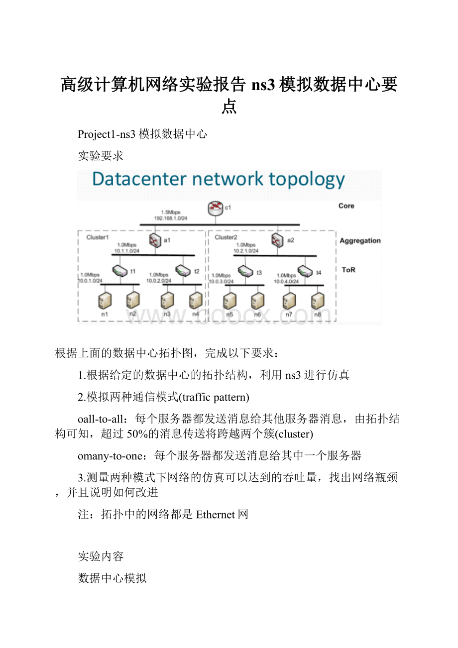
根据上面的数据中心拓扑图,完成以下要求:
1.根据给定的数据中心的拓扑结构,利用ns3进行仿真
2.模拟两种通信模式(trafficpattern)
oall-to-all:
每个服务器都发送消息给其他服务器消息,由拓扑结构可知,超过50%的消息传送将跨越两个簇(cluster)
omany-to-one:
每个服务器都发送消息给其中一个服务器
3.测量两种模式下网络的仿真可以达到的吞吐量,找出网络瓶颈,并且说明如何改进
注:
拓扑中的网络都是Ethernet网
实验内容
数据中心模拟
①实现及主要代码解释
a.设置自定义的attribute
为了做实验方便,设置如下自定义attribute:
∙pattern:
通信模式,all-to-all或many-to-one,默认为1
∙defaultDst:
多对一模式下,接收消息的默认服务器序号,默认为0
∙verbose:
enable或者disablePacketSink和OnOffApplication的日志,默认为false
∙DataRate1:
定义数据中心拓扑第一层的数据传输速率(Mbps),默认为1.0
∙DataRate2:
定义数据中心拓扑第二层的数据传输速率(Mbps),默认为1.0
∙DataRate3:
定义数据中心拓扑第三层的数据传输速率(Mbps),默认为1.5
实现代码如下:
uint16_tpattern=1;
uint16_tnodesNum=8;
uint16_tdefaultDst=0;
floatDataRate1=1.0;
floatDataRate2=1.0;
floatDataRate3=1.5;
uint16_tport=50000;
boolverbose=false;
CommandLinecmd;
cmd.AddValue("pattern","numberoftrafficpattern",pattern);//pattern1:
all-to-allpattern2:
many-to-one
cmd.AddValue("defaultDst","defaultdestinationservernodeinpattern2",defaultDst);
cmd.AddValue("DataRate1","datarateofcsmanetworkatlevel1",DataRate1);
cmd.AddValue("DataRate2","datarateofcsmanetworkatlevel2",DataRate2);
cmd.AddValue("DataRate3","datarateofcsmanetworkatlevel3",DataRate3);
cmd.AddValue("verbose","Tellsinkandonoffapplicationstologiftrue",verbose);
cmd.Parse(argc,argv);
LogComponentEnable("DataCenterSimulation",LOG_LEVEL_INFO);
if(verbose)
{
LogComponentEnable("PacketSink",LOG_LEVEL_INFO);
LogComponentEnable("OnOffApplication",LOG_LEVEL_INFO);
}
b.创建结点
根据实验要求,总共需要创建15个结点,包括:
∙8servers
∙4ToRswitches
∙2Aggregationswitches
∙1Coreswitch
实现代码如下:
//createnodes
NodeContainern1_8;
n1_8.Create(8);
NodeContainert1_4;
t1_4.Create(4);
NodeContainera12;
a12.Create
(2);
NodeContainerc1;
c1.Create
(1);
c.创建CSMA网络节点
整个数据中心网络拓扑从下往上可以分为三层,即
∙第一层:
由服务器与ToR组成的ethernet网络,共有4个,编号为CSMA11,CSMA12,CSMA13,CSMA14
∙第二层:
由ToR与Aggregation组成的ethernet网络,共有2个,编号为CSMA21,CSMA22
∙第三层:
由Aggregation与Core组成的ethernet网络,共有1个,编号为CSMA3
将创建好的15个网络结点分配到这7个CSMA网络中,实现代码如下:
//createcsmanodes
NodeContainercsmaNodes11=NodeContainer(n1_8.Get(0),n1_8.Get
(1),t1_4.Get(0));
NodeContainercsmaNodes12=NodeContainer(n1_8.Get
(2),n1_8.Get(3),t1_4.Get
(1));
NodeContainercsmaNodes13=NodeContainer(n1_8.Get(4),n1_8.Get(5),t1_4.Get
(2));
NodeContainercsmaNodes14=NodeContainer(n1_8.Get(6),n1_8.Get(7),t1_4.Get(3));
NodeContainercsmaNodes21=NodeContainer(t1_4.Get(0),t1_4.Get
(1),a12.Get(0));
NodeContainercsmaNodes22=NodeContainer(t1_4.Get
(2),t1_4.Get(3),a12.Get
(1));
NodeContainercsmaNodes3=NodeContainer(a12.Get(0),a12.Get
(1),c1.Get(0));
d.设置CSMA网络attribute,并将其安装到相应结点上
根据实验要求中的网络拓扑,设置相应网络的属性
∙所有直接相连的两个结点之间的延迟都为500ns
∙第一层和第二层CSMA网络的数据传输速率都为1.0Mbps,第三层为1.5Mbps
然后安装到相应的网络结点上,实现代码如下(DataRate可以通过命令行参数设置,默认值即为原实验要求):
//createthechannelsfirstwithoutanyIPaddressinginformation
CsmaHelpercsma1;
sprintf(buf,"%1.1fMbps",DataRate1);
csma1.SetChannelAttribute("DataRate",StringValue(buf));
csma1.SetChannelAttribute("Delay",StringValue("500ns"));
NetDeviceContainercsmaDevices11=csma1.Install(csmaNodes11);
NetDeviceContainercsmaDevices12=csma1.Install(csmaNodes12);
NetDeviceContainercsmaDevices13=csma1.Install(csmaNodes13);
NetDeviceContainercsmaDevices14=csma1.Install(csmaNodes14);
CsmaHelpercsma2;
sprintf(buf,"%1.1fMbps",DataRate2);
csma2.SetChannelAttribute("DataRate",StringValue(buf));
csma2.SetChannelAttribute("Delay",StringValue("500ns"));
NetDeviceContainercsmaDevices21=csma2.Install(csmaNodes21);
NetDeviceContainercsmaDevices22=csma2.Install(csmaNodes22);
CsmaHelpercsma3;
sprintf(buf,"%1.1fMbps",DataRate3);
csma3.SetChannelAttribute("DataRate",StringValue(buf));
csma3.SetChannelAttribute("Delay",StringValue("500ns"));
NetDeviceContainercsmaDevices3=csma3.Install(csmaNodes3);
e.分配网络IP
根据实验要求,为每个结点安装协议栈,并为7个CSMA网络分配IP,实现代码如下
//assignIPaddress
NS_LOG_INFO("AssignIPaddress.");
InternetStackHelperstack;
stack.Install(n1_8);
stack.Install(t1_4);
stack.Install(a12);
stack.Install(c1);
Ipv4AddressHelperaddress;
address.SetBase("10.0.1.0","255.255.255.0");
Ipv4InterfaceContainercsmaInterfaces11=address.Assign(csmaDevices11);
address.SetBase("10.0.2.0","255.255.255.0");
Ipv4InterfaceContainercsmaInterfaces12=address.Assign(csmaDevices12);
address.SetBase("10.0.3.0","255.255.255.0");
Ipv4InterfaceContainercsmaInterfaces13=address.Assign(csmaDevices13);
address.SetBase("10.0.4.0","255.255.255.0");
Ipv4InterfaceContainercsmaInterfaces14=address.Assign(csmaDevices14);
address.SetBase("10.1.1.0","255.255.255.0");
Ipv4InterfaceContainercsmaInterfaces21=address.Assign(csmaDevices21);
address.SetBase("10.2.1.0","255.255.255.0");
Ipv4InterfaceContainercsmaInterfaces22=address.Assign(csmaDevices22);
address.SetBase("192.168.1.0","255.255.255.0");
Ipv4InterfaceContainercsmaInterfaces3=address.Assign(csmaDevices3);
f.初始化路由表
这里直接调用了ns3自带的路由实现,实现代码如下
//Createrouternodes,initializeroutingdatabaseandsetuptherouting
//tablesinthenodes.
Ipv4GlobalRoutingHelper:
:
PopulateRoutingTables();
g.创建和分配PacketSink和OnOffClient
首先,创建sink和OnOff,实现代码如下
//CreatesinkAppandOnOffClient
ApplicationContainerclientApp[nodesNum][4];
ApplicationContainersinkApp[nodesNum];
然后,分配sink到所有的server结点上,实现代码如下(其中nodesNum表示server个数):
for(unsignedinti=0;i{
PacketSinkHelperpacketSinkHelper("ns3:
:
TcpSocketFactory",getAddress(i,port,csmaInterfaces11,csmaInterfaces12,csmaInterfaces13,csmaInterfaces14));
sinkApp[i]=packetSinkHelper.Install(n1_8.Get(i));
sinkApp[i].Start(Seconds(1.0));
sinkApp[i].Stop(Seconds(60.0));
}
再然后,分配OnOffClient到server结点上,并且根据pattern不同,进行不同的配置
∙pattern1:
每个服务器都发送消息给其他服务器消息,即发送消息给在另一个簇上面的4个服务器(每个服务器上建立4个OnOffClient)
∙pattern2:
每个服务器都发送消息给同一个服务器,可以默认为n1(每个服务器(n1除外)上建立1个OnOffClient)
实现代码如下
for(inti=0;i{
uint16_tdst=0;
if(pattern==1){//all-to-allpattern
for(intj=0;j<4;j++){
if(i<=3)
dst=j+4;
else
dst=j;
OnOffHelperclient("ns3:
:
TcpSocketFactory",getAddress(dst,port,csmaInterfaces11,csmaInterfaces12,csmaInterfaces13,csmaInterfaces14));
client.SetAttribute("OnTime",StringValue("ns3:
:
ConstantRandomVariable[Constant=50]"));
client.SetAttribute("OffTime",StringValue("ns3:
:
ConstantRandomVariable[Constant=0]"));
client.SetAttribute("DataRate",DataRateValue(DataRate("1.0Mbps")));
client.SetAttribute("PacketSize",UintegerValue(2000));
clientApp[i][j]=client.Install(n1_8.Get(i));
clientApp[i][j].Start(Seconds(1.0));
clientApp[i][j].Stop(Seconds(51.0));
sprintf(buf,"OnOffClient@Node%daimsatServer@Node%d",i+1,dst+1);
NS_LOG_INFO(buf);
}
}elseif(pattern==2){//many-to-onepattern
if(i==defaultDst)continue;
dst=defaultDst;
OnOffHelperclient("ns3:
:
TcpSocketFactory",getAddress(dst,port,csmaInterfaces11,csmaInterfaces12,csmaInterfaces13,csmaInterfaces14));
client.SetAttribute("OnTime",StringValue("ns3:
:
ConstantRandomVariable[Constant=50]"));
client.SetAttribute("OffTime",StringValue("ns3:
:
ConstantRandomVariable[Constant=0]"));
client.SetAttribute("DataRate",DataRateValue(DataRate("1.0Mbps")));
client.SetAttribute("PacketSize",UintegerValue(2000));
clientApp[i][0]=client.Install(n1_8.Get(i));
clientApp[i][0].Start(Seconds(1.0));
clientApp[i][0].Stop(Seconds(51.0));
sprintf(buf,"OnOffClient@Node%daimsatServer@Node%d",i+1,dst+1);
NS_LOG_INFO(buf);
}
这里解释一下一个函数
∙getAddress:
根据server的标号产生相应的IP:
port地址
getAddress实现代码如下
InetSocketAddressgetAddress(inti,uint16_tport,Ipv4InterfaceContaineri1,Ipv4InterfaceContaineri2,Ipv4InterfaceContaineri3,Ipv4InterfaceContaineri4){
switch(i){
case0:
returnInetSocketAddress(i1.GetAddress(0),port);break;
case1:
returnInetSocketAddress(i1.GetAddress
(1),port);break;
case2:
returnInetSocketAddress(i2.GetAddress(0),port);break;
case3:
returnInetSocketAddress(i2.GetAddress
(1),port);break;
case4:
returnInetSocketAddress(i3.GetAddress(0),port);break;
case5:
returnInetSocketAddress(i3.GetAddress
(1),port);break;
case6:
returnInetSocketAddress(i4.GetAddress(0),port);break;
case7:
returnInetSocketAddress(i4.GetAddress
(1),port);break;
default:
returnInetSocketAddress("10.0.0.1",port);
}
}
h.配置相应的trace
这里采用pcap文件来trace所有的device,方便利用wireshark来分析实验结果,实现代码如下
csma1.EnablePcapAll("DataCenterSimulation");
②实验结果与分析
a.pattern1实验结果
执行命令./waf--run"scratch/DC--pattern=1"(scratch/DC.cc为本次实验源程序文件),实验运行结果如下所示
从上面的结果可以看出,每个结点上的OnOffClient都有一半以上跨越了两个簇,产生的pcap文件如下所示
为了分析patten1的网络吞吐量,根据all-to-all模式下网络的对称性,选取测量位置
∙CSMA11:
通过servern1(node0/device0)来估计
∙CSMA21:
通过ToRt1(node8/device1)来估计
∙CSMA3 :
通过Aggregationa1(node12/device1)来估计
选取的测量标准为吞吐量,具体方法是
∙使用wireshark分析相应的pcap文件中的tcp包
∙使用statistics->TCPStreamGraph->ThroughputGraph来查看整个过程中该结点上的吞吐量变化情况
∙使用statistics->Summary来查看当前结点上网络平均吞吐量,以此估计相应CSMA网络的吞吐量
servern1上的测量结果如下
ThroughputGraph
Summary
ToRt1上的测量结果如下
ThroughputGraph
Summary
Aggregationa1上的测量结果如下
ThroughputGraph
Summary
b.pattern1实验结果分析
首先对实验结果进行简单汇总
网络
结点
带宽(Mbps)
网络平均吞吐量(Mbps)
CSMA11
servern1
1.0
0.255
CSMA21
ToRt1
1.0
0.541
CSMA3
Aggregationa1
1.5
0.993
从上面的结果可以看出
∙第1层CSMA网络平均吞吐量是0.255Mbps,带宽利用率为25.5%;
∙第2层CSMA网络平均吞吐量是0.541Mbps,带宽利用率为54.1%;
∙第3层CSMA网络平均吞吐量是0.993Mbps,带宽利用率为66.2%。
c.pattern1瓶颈及改进
∙瓶颈
根据以上的实验结果可以看出来,从网络的平均吞吐量来看:
第3层CSMA>第2层CSMA>第1层CSMA2,从带宽利用率上看也是这样,所以作为coreswitch连接两个子网络但带宽过小的第三层网络成了整个网络的瓶颈。
∙改进
可以加大第3层网络的带宽,防止数据流量过大出现拥塞的情况发生。
因此最后确定的网络带宽如下所示:
oCSMA11-14:
1.0Mbps
oCSMA21-22:
1.0Mbps
oCSMA3:
2.0Mbps
∙改进结果
执行命令行./waf--run"scratch/DC--DataRate1=1.0--DataRate2=1.0--DataRate3=2.0",以相同方式测量
 升级会员
升级会员 