TMS320C6678硬件设计说明英文版.docx
《TMS320C6678硬件设计说明英文版.docx》由会员分享,可在线阅读,更多相关《TMS320C6678硬件设计说明英文版.docx(50页珍藏版)》请在冰豆网上搜索。

TMS320C6678硬件设计说明英文版
ProductName:
FMC6678
ProductID:
ProjectID:
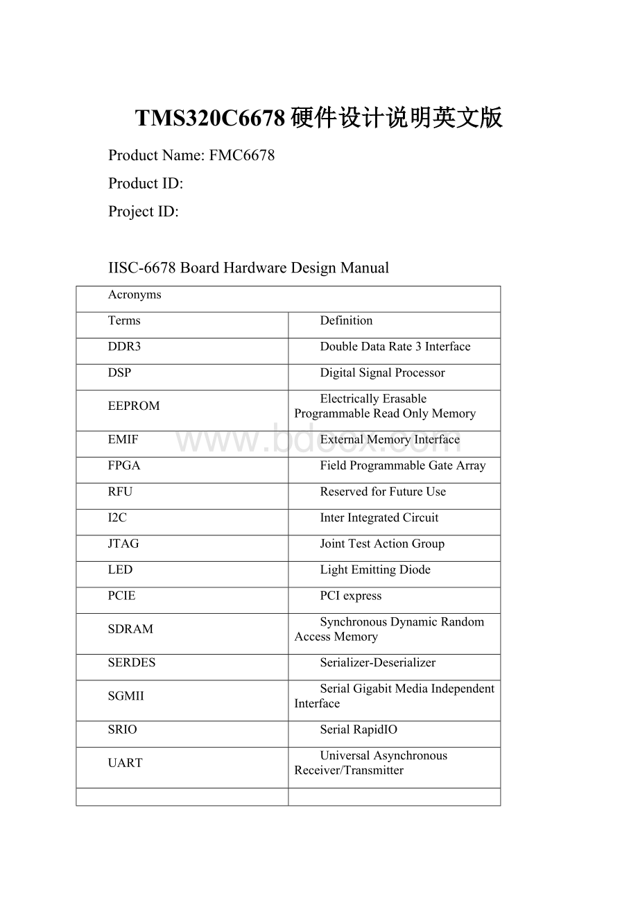
IISC-6678BoardHardwareDesignManual
Acronyms
Terms
Definition
DDR3
DoubleDataRate3Interface
DSP
DigitalSignalProcessor
EEPROM
ElectricallyErasableProgrammableReadOnlyMemory
EMIF
ExternalMemoryInterface
FPGA
FieldProgrammableGateArray
RFU
ReservedforFutureUse
I2C
InterIntegratedCircuit
JTAG
JointTestActionGroup
LED
LightEmittingDiode
PCIE
PCIexpress
SDRAM
SynchronousDynamicRandomAccessMemory
SERDES
Serializer-Deserializer
SGMII
SerialGigabitMediaIndependentInterface
SRIO
SerialRapidIO
UART
UniversalAsynchronousReceiver/Transmitter
ChinaResearchDevelopmentCenterforInternetofThings
InstituteofMicroelectronics,ChineseAcademyofSciences
InformationIdentification&SystemControlResearchCenter
2014-5-8
TableofContents
1.Overview
ThischapterprovidesanoverviewoftheIISC-6678alongwiththekeyfeaturesandblockdiagram.
1.1KeyFeatures
1.2FunctionalOverview
1.3BasicOperation
1.4ConfigurationSwitchSettings
1.5PowerSupply
1.1KeyFeatures
TheIISC-6678Boardisahighperformance,cost-efficient,standalonedevelopmentplatformthatenablesuserstoevaluateanddevelopapplicationsfortheTexasInstruments’TMS320C6678DigitalSignalProcessor(DSP).TheIISC-6678BoardalsoservesasahardwarereferencedesignplatformfortheTMS320C6678DSP.Schematics,codeexamplesandapplicationnotesareavailabletoeasethehardwaredevelopmentprocessandtoreducethetimetomarket.
ThekeyfeaturesoftheIISC-6678Boardare:
⏹TexasInstruments'multi-coreDSP–TMS320C6678
⏹512MbytesofDDR3-1333Memory
⏹64MbytesofNANDFlash
⏹16MBSPINORFLASH
⏹TwoGigabitEthernetportssupporting10/100/1000Mbpsdata-rateandoneRJ45/RS232
⏹160pinLPCFMCInterfacecontainingSRIO,PCIe,LVDSandPowerSupply
⏹HighPerformanceconnectorforHyperLinkconnector
⏹128K-byteI2CEEPROMforbooting
⏹UserLEDs,5BanksofDIPSwitchesand4Software-controlledLEDs
⏹TI60-PinJTAGheadertosupportallexternalemulatortypes
⏹PoweredbyDCpower-brickadapter(5V/8.0A)
1.2FunctionalOverview
TheTMS320C66x™DSPs(includingtheTMS320C6678device)arethehighest-performancefixed/floating-pointDSPgenerationintheTMS320C6000™DSPplatform.TheTMS320C6678deviceisbasedonthethird-generationhigh-performance,advancedVelociTI™very-long-instruction-word(VLIW)architecturedevelopedbyTexasInstruments(TI),designedspecificallyforhighdensitywireline/wirelessmediagatewayinfrastructure.ItisanidealsolutionforIPbordergateways,videotranscodingandtranslation,video-serverandintelligentvoiceandvideorecognitionapplications.TheC66xdevicesarebackwardcode-compatiblefrompreviousdevicesthatarepartoftheC6000™DSPplatform.
ThefunctionalblockdiagramofIISC-6678Boardisshowninthefigurebelow:
Figure1.1BlockDiagramofIISC-6678Board
1.3BasicOperation
TheIISC-6678platformisdesignedtoworkwithTI’sCodeComposerStudio(CCS)developmentenvironmentandshipswithaversionspecificallytailoredforthisboard.CCScaninterfacewiththeboardthroughanexternalemulator.
Tostartoperatingtheboard,followinstructionsintheQuickStartGuide,toinstallallthenecessarydevelopmenttools,driversanddocumentation.
Aftertheinstallationhascompleted,followthestepsbelowtorunCodeComposerStudio.
1.ConnectUSBcablefromhostPCtoIISC-6678Board.
2.Power-ontheboardusingthepowerbrickadapter(5V/8.0A)suppliedalongwiththisIISC-6678Board.
3.LaunchCodeComposerStudiofromhostPCbydoubleclickingonitsicononthePCdesktop.
Figure1.2IISC-6678BoardLayout
1.4BootModeandBootConfigurationSwitchSetting
TheIISC-6678Boardhas20slidingDIPswitches(BoardRef.SW2toSW6)todeterminebootmode,bootconfiguration,devicenumber,Endianmode,CorePacPLLclockselectionandPCIeModeselectionoptionslatchedatresetbytheDSP.
1.5PowerSupply
TheIISC-6678Boardcanbepoweredfromasingle+5V/8.0ADC(40W)externalpowersupplyconnectedtotheDCpowerjack(JP1).Internally,+5VinputisconvertedintorequiredvoltagelevelsusinglocalDC-DCconverters.
⏹DSPA_CVDD(+0.90V~+1.1V)usedfortheDSPCorelogic
⏹VCC1V0isusedforDSPinternalmemoryandHyperLink/SRIO/SGMII/PCIeSERDESterminationofDSP
⏹VCC1V5isusedforDDR3buffersofDSP,HyperLink/SRIO/SGMII/PCIeSERDESregulatorsinDSPandDDR3DRAMchips
⏹VCC1V8isusedforDSPPLLs,DSPLVCMOSI/OsandFPGAI/OsdrivingtheDSP
⏹+1.8VisusedforFPGAI/OsdrivingtheDSP
⏹+2.5VisusedforGigabitEthernetPHYcore
⏹+1.2VisusedforFPGAcoreandGigabitEthernetPHYcore
2.IntroductiontotheIISC-6678Board
ThischapterprovidesanintroductionanddetailsofinterfacesfortheIISC-6678Board.Itcontains:
2.1IISC-6678BoardBootmodeandBootconfigurationswitchsettings
2.2JTAG-EmulationOverview
2.3ClockDomains
2.4I2CbootEEPROM/SPINORFlash
2.5UART
2.6FPGA
2.7GigabitEthernetPHY
2.8SerialRapidIO(SRIO)Interfaces
2.9DDR3ExternalMemoryInterfaces
2.1016-bitAsynchronousExternalMemoryInterface
2.11HyperLinkInterface
2.12PCIeInterface
2.13FMCInterface
2.1IISC-6678BoardBootModeandBootConfigurationSwitchSettings
TheIISC-6678BoardhasfiveconfigurationDIPswitches:
SW2,SW3,SW4,SW5andSW6thatcontain17individualvalueslatchedwhenresetisreleased.Thisoccurswhenpowerisappliedtheboard,aftertheuserpressestheFULL_RESETpushbutton.
SW2determinesgeneralDSPconfiguration,littleorBigEndianmodeandbootdeviceselection.
SW3,SW4,SW5andSW6determineDSPbootdeviceconfiguration,CorePacPLLsettingandPCIemodeselectionandenable.
Figure2.1IISC-6678BoardBootModeandConfiguration
2.2JTAG-EmulationOverview
TheTI60-pinJTAGheader(EMU1)isprovidedforhighspeedreal-timeemulation.TheTI60-pinJTAGsupportsallstandardTIDSPemulators.Anadapterwillberequiredforusewithsomeemulators.
ThesecondwayofaccessingtheDSPisthroughtheDSP_JTAGport.
TheJTAGinterfaceamongtheDSP,externalemulatorandDSP_JTAGconnectorisshowninthebelowfigure.
Figure2.2IISC-6678BoardJTAGemulation
2.3ClockDomains
TheIISC-6678BoardincorporatesavarietyofclockstotheTMS320C6678aswellasotherdeviceswhichareconfiguredautomaticallyduringthepowerupconfigurationsequence.ThefigurebelowillustratesclockingforthesystemintheIISC-6678Boardmodule.
Figure2.3IISC-6678BoardClockDomains
2.4I2CBootEEPROM/SPINORFlash
TheI2CmodulesontheTMS320C6678maybeusedbytheDSPtocontrollocalperipheralICs(DACs,ADCs,etc.)ormaybeusedtocommunicatewithothercontrollersinasystemortoimplementauserinterface.
TheI2CbusisconnectedtooneEEPROM.
Theserialperipheralinterconnect(SPI)moduleprovidesaninterfacebetweentheDSPandotherSPI-compliantdevices.TheprimaryintentofthisinterfaceistoallowforconnectiontoaSPIROMforboot.TheSPImoduleonTMS320C6678issupportedonlyinMastermode.
TheNORFLASHattachedtoCS0zontheTMS320C6678isaNUMONYXN25Q128A21.ThisNORFLASHsizeis16MB.ItcancontaindemonstrationprogramssuchasPOSTortheOOBdemonstration.TheCS1zoftheSPIisusedbytheDSPtoaccessregisterswithintheFPGA.
Figure2.4IISC-6678BoardSPI/EEPROMConnections
2.5UART
Thefigure2.5illustratestheUARTconnectionsontheIISC-6678Board.
Figure2.5IISC-6678BoardUARTConnections
2.6FPGA
TheFPGA(XilinxXC3S200AN)controlstheresetmechanismoftheDSPandprovidesbootmodeandbootconfigurationdatathroughSW2,SW3,SW4,SW5andSW6.TheFPGAalsosupports4userLEDsand1userswitchthroughcontrolregisters.
AllFPGAregistersareaccessibleovertheSPIinterface.
ThefigurebelowshowstheinterfacebetweenTMS320C6678DSPandFPGA.
Figure2.6IISC-6678BoardFPGAConnections
2.7GigabitEthernetConnections
TheIISC-6678BoardprovidesconnectivityforbothSGMIIGigabitEthernetports.Theseareshowninfigurebelow:
Figure2.7IISC-6678BoardEthernetRouting
TheEthernetPHYisconnectedtoDSPEMACtoprovideacopperinterfaceandroutedtoaGigabitRJ-45connector.
2.8SerialRapidIO(SRIO)Interface
TheIISC-6678BoardsupportshighspeedSERDESbasedSerialRapidIO(SRIO)interface.
Therearetotal4RapidIOportsavailableonTMS320C6678.AllSRIOportsareroutedtoFMCedgeconnectoronboard.BelowfigureshowsRapidIOconnectionsbetweentheDSPandFMCedgeconnector.
Figure2.8IISC-6678BoardSRIOPortConnections
2.9DDR3ExternalMemoryInterface
TheTMS320C6678DDR3interfaceconnectstofive1Gbit(64Megx16)DDR31333devices.
Thisconfigurationallowstheuseofboth“narrow(16-bit)”,“normal(32-bit)”,and“wide(64-bit)”modesoftheDDR3EMIF.
SAMSUNGDDR3K4B1G1646x-HCH9SDRAMs(64Mx16;667MHz)areusedontheDDR3EMIF.
Thefigure2.9illustratestheimplementationfortheDDR3SDRAMmemory.
Figure2.9IISC-6678BoardSDRAM
2.1016-bitAsynchronousExternalMemoryInterface(EMIF-16)
TheTMS320C6678EMIF-16interfaceconnectstoone512Mbit(64MB)NANDflashdeviceontheIISC-6678Board.TheEMIF16moduleprovidesaninterfacebetweenDSPandasynchronousexternalmemoriessuchasNANDandNORflash.Formoreinformation,seetheExternalMemoryInterface(EMIF16)forKeyStoneDevicesUserGuide(literaturenumberSPRUGZ3).
NUMONYX_NAND512R3A2SZA6ENANDflash(64MB)isusedontheEMIF-16.
Thefigure2.10illustratestheEMIF-16connectionsontheIISC-6678Board.
Figure2.10IISC-6678BoardEMIF-16conn