实验5 图像频域增强文档格式.docx
《实验5 图像频域增强文档格式.docx》由会员分享,可在线阅读,更多相关《实验5 图像频域增强文档格式.docx(9页珍藏版)》请在冰豆网上搜索。

2
3
4
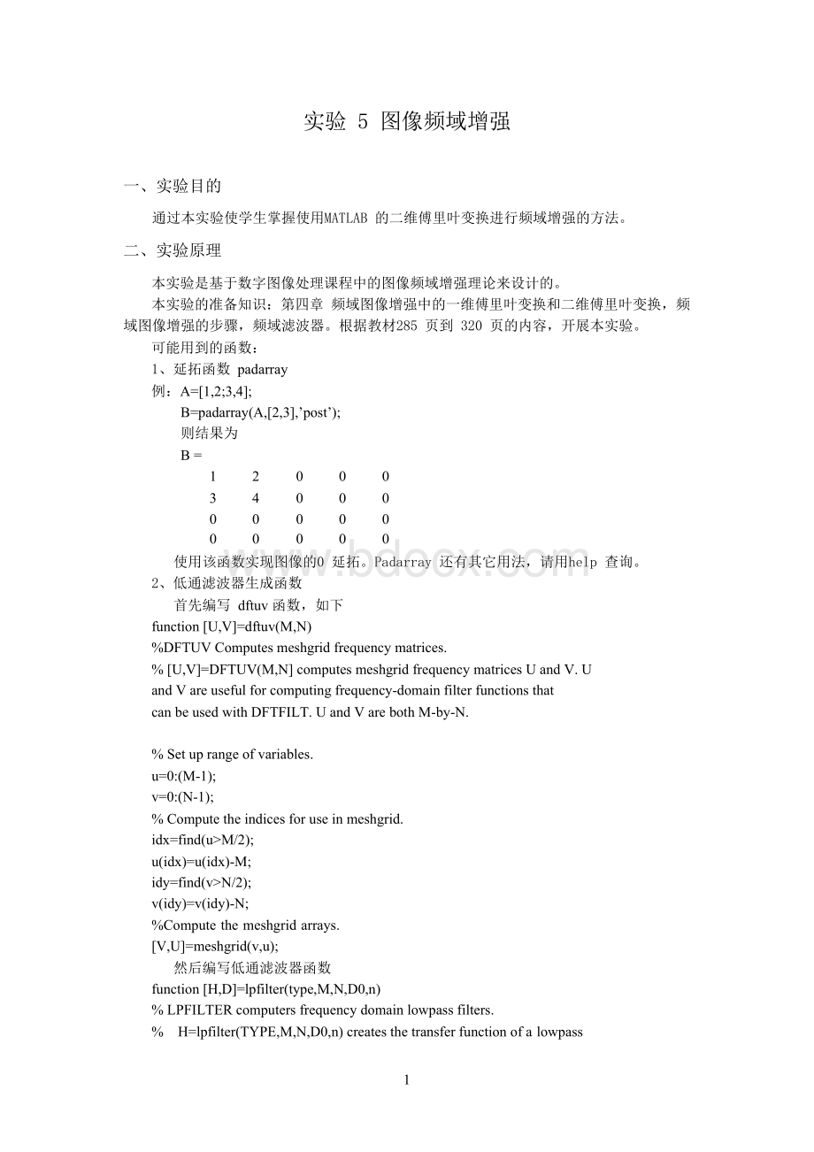
使用该函数实现图像的0延拓。
Padarray还有其它用法,请用help查询。
2、低通滤波器生成函数
首先编写dftuv函数,如下
function[U,V]=dftuv(M,N)
%DFTUVComputesmeshgridfrequencymatrices.
%[U,V]=DFTUV(M,N]computesmeshgridfrequencymatricesUandV.UandVareusefulforcomputingfrequency-domainfilterfunctionsthat
canbeusedwithDFTFILT.UandVarebothM-by-N.
%Setuprangeofvariables.u=0:
(M-1);
v=0:
(N-1);
%Computetheindicesforuseinmeshgrid.idx=find(u>
M/2);
u(idx)=u(idx)-M;
idy=find(v>
N/2);
v(idy)=v(idy)-N;
%Computethemeshgridarrays.[V,U]=meshgrid(v,u);
然后编写低通滤波器函数
function[H,D]=lpfilter(type,M,N,D0,n)
%LPFILTERcomputersfrequencydomainlowpassfilters.
% H=lpfilter(TYPE,M,N,D0,n)createsthetransferfunctionofalowpass
9
filter,H,ofthespecifiedTYPEandsize(M-by-N).Toviewthefilterasanimageormeshplot,itshouldbecenteredusingH=fftshift(H).
%validvaluesforTYPE,D0,andnare:
% '
ideal'
IdeallowpassfilterwithcutofffrequencyD0.nneednotbesupplied.D0mustbepositive.
btw'
Butterworthlowpassfilterofordern,andcutoffD0.Thedefaultvaluefornis1.D0mustbepositive.
gaussian'
Gaussianlowpassfilterwithcutoff(standarddeviation)D0.
nneednotbesupplied.D0mustbepositive.
%Usefunctiondftuvtosetupthemeshgridarraysneededforcomputingtherequireddistances.
[U,V]=dftuv(M,N);
%
D=sqrt(U.^2+V.^2);
%ComputethedistancesD(U,V)
%Beginfiltercomputations.switchtype
case'
H=double(D<
=D0);
case'
ifnargin==4n=1;
end
�endH=1./(1+(D./D0).^(2*n));
H=exp(-(D.^2)./(2*(D0^2)));
otherwise
error('
Unknownfiltertype'
)
通过调用函数lpfilter可生成相应的滤波器掩膜矩阵。
参考该函数可相应的生成高通滤波器函数。
3、频域滤波
F=fft2(f,size(H,1),size(H,2));
%对延拓的f计算FFT。
注意,这里隐含着对f的延拓。
G=real(ifft2(H.*F));
%滤波
Gf=G(p>
裁剪后的图像
三、实验内容
(一)图像频域增强的步骤
参考教材286页的Figure4.36,重复该图像中的步骤,并将相应的结果显示出来。
(二)频域低通滤波
产生实验四中的白条图像。
设计不同截止频率的理想低通滤波器、Butterworth低通滤波器,对其进行频域增强。
观察频域滤波效果,并解释之。
设计不同截止频率的理想低通滤波器、Butterworth低通滤波器,对含高斯噪声的lena
图像进行频域增强。
(三)频域高通滤波
设计不同截止频率的理想高通滤波器、Butterworth高通滤波器,对上述白条图像进行频域增强。
设计不同截止频率的理想高通滤波器、Butterworth高通滤波器,对含高斯噪声的lena
四、实验步骤
(二)频域低通滤波理想低通滤波器
1.D0=5
程序:
A=zeros(64,64);
A(32-20:
32+20,32-8:
32+8)=255;
subplot(1,2,1)imshow(A);
s=fftshift(fft2(A));
[M,N]=size(s);
n1=floor(M/2);
%对M/2进行取整
n2=floor(N/2);
d0=5;
fori=1:
M
forj=1:
N
d=sqrt((i-n1)^2+(j-n2)^2);
%点(i,j)到傅立叶变换中心的距离
h=1*exp(-1/2*(d^2/d0^2));
%GLPF滤波函数
s(i,j)=h*s(i,j);
%GLPF滤波后的频域表示
s=ifftshift(s);
s=uint8(real(ifft2(s)));
subplot(1,2,2);
%创建图形图像对象
imshow(s);
运行结果:
2.D0=50
d0=50;
Butterworth低通滤波器
1.程序
%点(i,j)到傅立叶变换中心的距离h=1/(1+0.414*(d/d0)^(2*n));
�
�s(i,j)=h*s(i,j);
含高斯噪声的lena图像进行频域增强
clearall;
A=imread('
D:
\pic\lena.bmp'
)subplot(2,3,1),imshow(A,[]);
title('
原图'
) %把图像显示出来
B=imnoise(A,'
gauss'
0.02)
subplot(2,3,3),imshow(B,[]);
%添加高斯噪声后的图像
添加高斯噪声后的图像'
f=double(B);
%图像存储类型转换
g=fft2(f);
%傅立叶变换
g=fftshift(g);
%转换数据矩阵
[N1,N2]=size(g);
%测量图像尺寸参数
n=2;
n1=fix(N1/2);
n2=fix(N2/2);
fori=1:
N1
N2
d=sqrt((i-n1)^+(j-n2)^2)c=double(d<
=d0);
%result(i,j)=c*g(i,j);
resul=ifftshift(result);
%傅立叶逆变换
X2=ifft2(result);
X3=uint8(real(X2));
subplot(2,3,5)
imshow(X3) %显示频域增强后的图像
D0=50,低通滤波器'
原图 添加高斯噪声后的图像
D0=20,butterworth 滤波器
D0=20,低通滤波器
(三)频域高通滤波理想高通滤波器A=zeros(64,64);
subplot(1,2,1);
imshow(A);
s=fftshift(fft2(A));
%对M/2进行取整
�D0=50,低通滤波器
D0=50,butterwort滤h波器
%点(i,j)到傅立叶变换中心的距离
h=1-(1*exp(-1/2*(d^2/d0^2)));
s=uint8(real(ifft2(s)));
subpl