EDA作业课案.docx
《EDA作业课案.docx》由会员分享,可在线阅读,更多相关《EDA作业课案.docx(16页珍藏版)》请在冰豆网上搜索。
EDA作业课案
信号发生器设计
1.设计原理
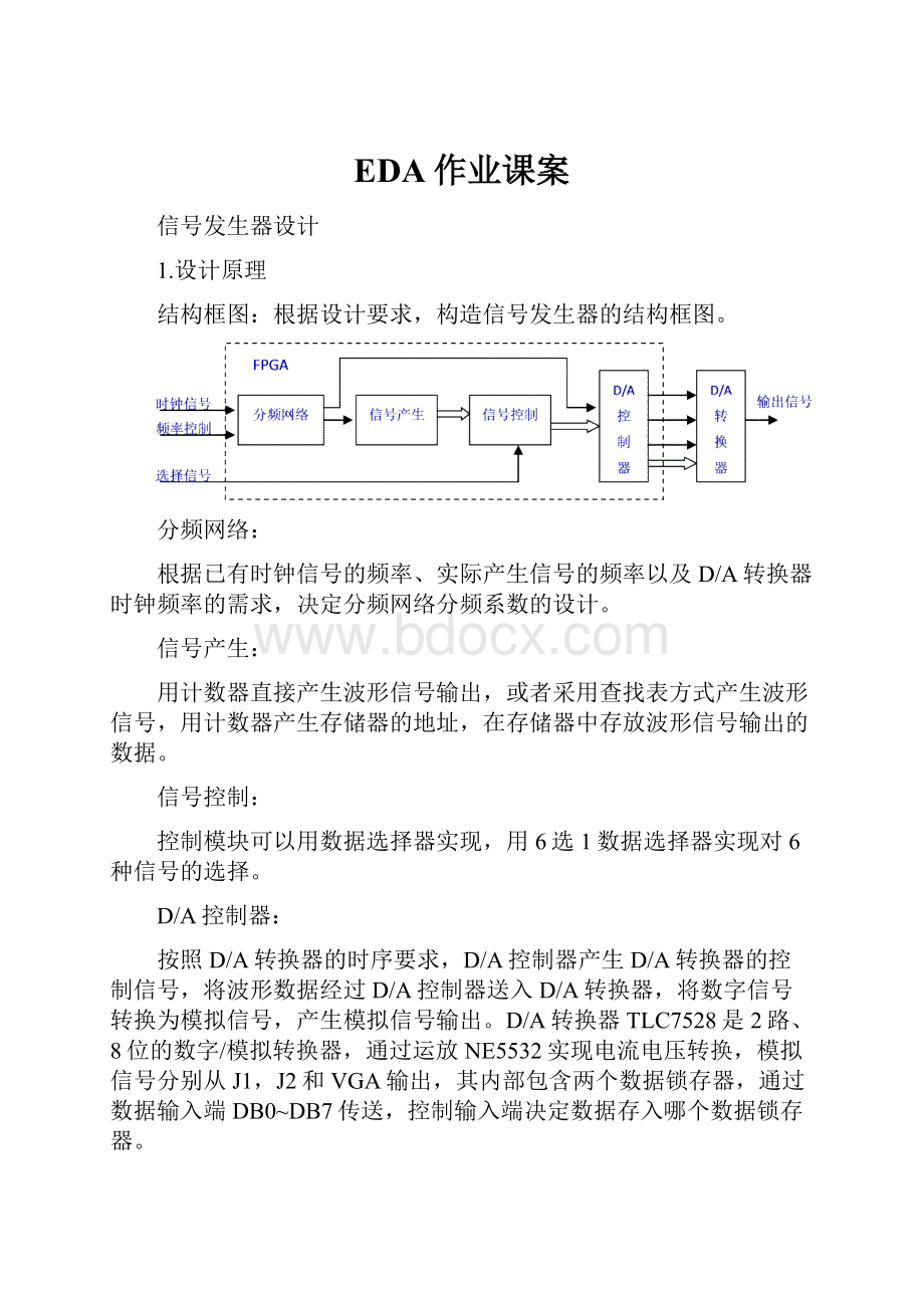
结构框图:
根据设计要求,构造信号发生器的结构框图。
分频网络:
根据已有时钟信号的频率、实际产生信号的频率以及D/A转换器时钟频率的需求,决定分频网络分频系数的设计。
信号产生:
用计数器直接产生波形信号输出,或者采用查找表方式产生波形信号,用计数器产生存储器的地址,在存储器中存放波形信号输出的数据。
信号控制:
控制模块可以用数据选择器实现,用6选1数据选择器实现对6种信号的选择。
D/A控制器:
按照D/A转换器的时序要求,D/A控制器产生D/A转换器的控制信号,将波形数据经过D/A控制器送入D/A转换器,将数字信号转换为模拟信号,产生模拟信号输出。
D/A转换器TLC7528是2路、8位的数字/模拟转换器,通过运放NE5532实现电流电压转换,模拟信号分别从J1,J2和VGA输出,其内部包含两个数据锁存器,通过数据输入端DB0~DB7传送,控制输入端决定数据存入哪个数据锁存器。
通过状态机实现FPGA对TLC7528的控制,按要求依次输出控制信号。
FPGA的dac输出信号与TLC7528的相连,FPGA的data输出信号与TLC7528的数据输入端相连,FPGA的cs和wr输出信号分别与TLC7528的CS和WR相连。
信号产生:
递增锯齿波利用计数器产生递增锯齿波信号。
设计复位信号reset使输出清零,高电平有效;reset为低电平时,在输入时钟信号clk的作用下,设计一个8位二进制加法计数器,输出信号依次从全0变为全1,计为全1后恢复为全0,不断循环,从而产生递增锯齿波信号输出。
正弦波信号利用ROM产生正弦波信号。
首先用计数器产生存储器的地址,接着读取存放在存储器中的正弦波信号数据。
2.实现过程
信号发生器的设计:
采用混合描述的层次化设计方案,在调用这些子模块,采用原理图方式实现信号发生器的系统电路连接。
子模块的设计有:
a.递减锯齿波signal2的设计实现
b.三角波signal3的设计实现
c.阶梯波signal4的设计实现
d.方波信号signal5的设计实现
e.正弦信号signal6的设计实现
f.数据选择器mux61设计实现:
数据选择器的选择端信号sel[2..0]共3位,数据端共6组,每组信号均是8位,分别是d1[7..0]、…、d7[7..0],输出信号q[7..0]。
g.分频网络设计实现:
利用二进制计数器的分频实现。
通过将计数器状态输出端的信号引出,即可得到不同的频率信号。
3.顶层原理图
连接三个模块电路:
信号发生器电路signal7、分频网络fclk以及DAC控制模块dac_control连接在一起,
将FPGA的输出信号cs、wr、dac_ac和data[7..0]与TLC7528对应引脚相连,将程序下载到目标芯片中,用示波器观察输出波形,若运行结果正确,可以实现各种波形的选择输出。
电路signal7是将递增锯齿波信号模块signal1、递减锯齿波信号模块signal2、三角波信号模块signal3、阶梯波信号模块signal4、方波信号模块signal5、正弦信号模块signal6和数据选择器mux61电路连接形成。
4.子程序
递增锯齿波信号signal1的程序:
libraryieee;
useieee.std_logic_1164.all;
useieee.std_logic_unsigned.all;
entitysignal1is--产生递增锯齿波模块signal1
port(clk,reset:
instd_logic;--复位信号reset,时钟信号clk
q:
outstd_logic_vector(7downto0));--输出信号q,8位数字信号
endsignal1;
architectureaofsignal1is
begin
process(clk,reset)
variabletmp:
std_logic_vector(7downto0);
begin
ifreset='1'then--复位信号reset=1有效,启始状态
tmp:
="00000000";
elsifrising_edge(clk)then--复位信号无效,时钟信号有上升沿
iftmp="11111111"then--计数值全1,恢复到全0状态
tmp:
="00000000";
else
tmp:
=tmp+1;--加法计数
endif;
endif;
q<=tmp;--信号输出,产生递增锯齿波信号
endprocess;
enda;
递减锯齿波signal2的程序:
libraryieee;
useieee.std_logic_1164.all;
useieee.std_logic_unsigned.all;
entitysignal2is--递减锯齿波signal2
port(clk,reset:
instd_logic;--复位信号reset,时钟信号clk
q:
outstd_logic_vector(7downto0));--输出信号q,8位数字信号
endsignal2;
architectureaofsignal2is
begin
process(clk,reset)
variabletmp:
std_logic_vector(7downto0);
begin
ifreset='1'then--复位信号reset=1有效,启始状态零
tmp:
="11111111";
elsifrising_edge(clk)then--复位信号无效,时钟信号有上升沿
iftmp="00000000"then--计数值全0,恢复到全1状态
tmp:
="11111111";
else
tmp:
=tmp-1;--减法计数
endif;
endif;
q<=tmp;--信号输出,产生递减锯齿波信号
endprocess;
enda;
三角波signal3的程序:
libraryieee;
useieee.std_logic_1164.all;
useieee.std_logic_unsigned.all;
entitysignal3is--三角波signal3
port(clk,reset:
instd_logic;--复位信号reset,时钟信号clk
q:
outstd_logic_vector(7downto0));--输出信号q,8位数字信号
endsignal3;
architectureaofsignal3is
begin
process(clk,reset)
variabletmp:
std_logic_vector(7downto0);
variablea:
std_logic;
begin
ifreset='1'then
tmp:
="00000000";
elsifrising_edge(clk)then
ifa='0'then--a=0,实现加法计数
iftmp="11111110"then
tmp:
="11111111";--加法计数全1时,令a=1
a:
='1';
else
tmp:
=tmp+1;--加法计数
endif;
else
iftmp="00000001"then
tmp:
="00000000";--减法计数全0时,令a=0
a:
='0';
else
tmp:
=tmp-1;--减法计数
endif;
endif;
endif;
q<=tmp;--信号输出,产生三角波
endprocess;
enda;
阶梯波signal4的程序:
libraryieee;
useieee.std_logic_1164.all;
useieee.std_logic_unsigned.all;
entitysignal4is--阶梯波signal4
port(clk,reset:
instd_logic;--复位信号reset,时钟信号clk
q:
outstd_logic_vector(7downto0));--输出信号q,8位数字信号
endsignal4;
architectureaofsignal4is
begin
process(clk,reset)
variabletmp:
std_logic_vector(7downto0);
begin
ifreset='1'then
tmp:
="00000000";
elsifrising_edge(clk)then
iftmp="11111111"then
tmp:
="00000000";
else
tmp:
=tmp+16;--阶梯信号的产生,阶梯变化值=16
endif;
endif;
q<=tmp;
endprocess;
enda;
方波信号signal5的程序:
libraryieee;
useieee.std_logic_1164.all;
useieee.std_logic_unsigned.all;
entitysignal5is--方波signal5
port(clk,reset:
instd_logic;--复位信号reset,时钟信号clk
q:
outstd_logic_vector(7downto0));--输出信号q,8位数字信号
endsignal5;
architectureaofsignal5is
signala:
std_logic;
begin
process(clk,reset)
variabletmp:
std_logic_vector(7downto0);
begin
ifreset='1'then
a<='0';
elsifrising_edge(clk)then
iftmp="11111111"then--产生8位二进制计数
tmp:
="00000000";
else
tmp:
=tmp+1;
endif;
iftmp<"10000000"then--计数值<1000000,a=1
a<='1';
else--否则a=0
a<='0';
endif;
endif;
endprocess;
process(clk,a)
begin
ifrising_edge(clk)then
ifa='1'then--a=1时,输出全1
q<="11111111";
else
q<="00000000";--a=0时,输出全0
endif;
endif;
endprocess;
enda;
正玄信号signal6的程序:
libraryieee;
useieee.std_logic_1164.all;
useieee.std_logic_unsigned.all;
entitysinis
port(clk,reset:
instd_logic;
q:
outintegerrange0to255);
endsin;
architectureaaofsinis
begin
process(clk,reset)
variablea:
integerrange0to63;
begin
ifreset='0'then
q<=0;
elsifclk'eventandclk='1'then
ifa=63then
a:
=0;
else
a:
=a+1;
endif;
caseais
when0=>q<=255;when1=>q<=254;when2=>q<=252;
when3=>q<=249;when4=>q<=245;when5=>q<=239;
when6=>q<=233;when7=>q<=225;when8=>q<=217;
when9=>q<=207;when10=>q<=197;when11=>q<=186;
when12=>q<=174;when13=>q<=162;when14=>q<=150;
when15=>q<=137;when16=>q<=124;when17=>q<=112;
when18=>q<=99;when19=>q<=87;when20=>q<=75;
when21=>q<=64;when22=>q<=53;when23=>q<=43;
when24=>q<=34;when25=>q<=26;when26=>q<=19;
when27=>q<=13;when28=>q<=8;when29=>q<=4;
when30=>q<=1;when31=>q<=0;when32=>q<=0;
when33=>q<=1;when34=>q<=4;when35=>q<=8;
when36=>q<=13;when37=>q<=19;when38=>q<=26;
when39=>q<=34;when40=>q<=43;when41=>q<=53;
when42=>q<=64;when43=>q<=75;when44=>q<=87;
when45=>q<=99;when46=>q<=112;when47=>q<=124;
when48=>q<=137;when49=>q<=150;when50=>q<=162;
when51=>q<=174;when52=>q<=186;when53=>q<=197;
when54=>q<=207;when55=>q<=217;when56=>q<=255;
when57=>q<=233;when58=>q<=239;when59=>q<=245;
when60=>q<=249;when61=>q<=252;when62=>q<=254;
when63=>q<=255;whenothers=>null;
endcase;
endif;
endprocess;
endaa;
FPGA的分频模块程序:
libraryIEEE;
useIEEE.std_logic_1164.all;
useieee.std_logic_unsigned.all;
entityfclkis--端口信号定义
port(clk,speed:
instd_logic;
fclk:
outstd_logic;
fclk_dac:
inoutstd_logic);
endfclk;
architecturebehoffclkis
signalf:
std_logic_vector(7downto0);--定义中间信号f(7..0)
signalf3:
std_logic_vector(2downto0);--定义中间信号f3(2..0)
Begin
process(clk)--八位二进制加法计数器敏感信号clk
begin
ifclk'eventandclk='1'then--时钟信号clk上升沿
f<=f+1;--计数器f加1
endif;
endprocess;
process(clk,speed,f)
begin
ifclk'eventandclk='1'then--产生输出时钟fclk_dac
ifspeed='1'then--speed=1时,四分频高频时钟输出,fclk_dac=f
(1)
fclk_dac<=f
(1);
elsefclk_dac<=f(3);--speed=0时,十六分频低频时钟输出,fclk_dac=f(3)
endif;
endif;
endprocess;
process(fclk_dac)--三位二进制加法计数器敏感信号fclk_dac
begin
iffclk_dac'eventandfclk_dac='1'then--时钟信号fclk_dac上升沿
f3<=f3+1;--计数器f3加1
endif;
endprocess;
process(fclk_dac)--产生输出时钟fclk敏感信号fclk_dac
begin
iffclk_dac'eventandfclk_dac='1'then--时钟信号fclk_dac上升沿
iff3="10"then--当f3=10时,fclk=1
fclk<='1';
elsefclk<='0';--当f3≠10时,fclk=0
endif;
endif;
endprocess;
endbeh;
数据选择器mux61程序:
libraryieee;
useieee.std_logic_1164.all;
useieee.std_logic_unsigned.all;
entitymux61is
port(sel:
instd_logic_vector(2downto0);--选择信号sel
d1,d2,d3,d4,d5,d6:
instd_logic_vector(7downto0);--6路输入信号
q:
outstd_logic_vector(7downto0));--被选择信号输出
endmux61;
architectureaofmux61is
begin
process(sel)
begin
caseselis
when"001"=>q<=d1;--选择信号sel=001,选择第1路信号输出
when"010"=>q<=d2;--选择信号sel=010,选择第2路信号输出
when"011"=>q<=d3;--选择信号sel=011,选择第3路信号输出
when"100"=>q<=d4;--选择信号sel=100,选择第4路信号输出
when"101"=>q<=d5;--选择信号sel=101,选择第5路信号输出
when"110"=>q<=d6;--选择信号sel=110,选择第6路信号输出
whenothers=>null;
endcase;
endprocess;
enda;
FPGA的模数控制程序:
libraryieee;
useieee.std_logic_1164.all;
useieee.std_logic_arith.all;
useieee.std_logic_unsigned.all;
entitydac_controlis
port(--端口信号定义
fclk,reset:
instd_logic;
datain:
instd_logic_vector(7downto0);
cs,wr,dac_ab:
outstd_logic;
data:
outstd_logic_vector(7downto0)
);
end;
architecturebehaveofdac_controlis
typestatesis(st1,st2,st3);
signalstate:
states;
begin
process(fclk,reset,state)
variabled_buff:
std_logic_vector(7downto0);
begin
ifreset='1'then--系统复位
d_buff:
="00000000";
state<=st1;
else
If(fclk'eventandfclk='1')then
casestateis
whenst1=>--st1状态,起始状态
wr<='1';dac_ab<='1';cs<='1';
state<=st2;
whenst2=>--st2状态,准备模数转换
cs<='0';dac_ab<='0';wr<='0';--设置TLC7528控制信号
state<=st3;
whenst3=>--st3状态,采集待转换的数据
d_buff:
=datain;state<=st1;
whenothers=>
state<=st1;
endcase;
endif;
endif;
data<=d_buff;--待转换数据送TLC7528,实现数模转换
endprocess;
endbehave;
5.实验结果
将FPGA的输出信号cs、wr、dac_ac和data[7..0]与TLC7528对应引脚相连,将
程序下载到目标芯片中,用示波器观察输出波形,拨动开关分别切换六种波形,
运行结果基本正确,可以实现各种波形的选择输出,但波形正幅值方向有失真现
象。
 升级会员
升级会员 