三极管参数等.docx
《三极管参数等.docx》由会员分享,可在线阅读,更多相关《三极管参数等.docx(12页珍藏版)》请在冰豆网上搜索。
三极管参数等
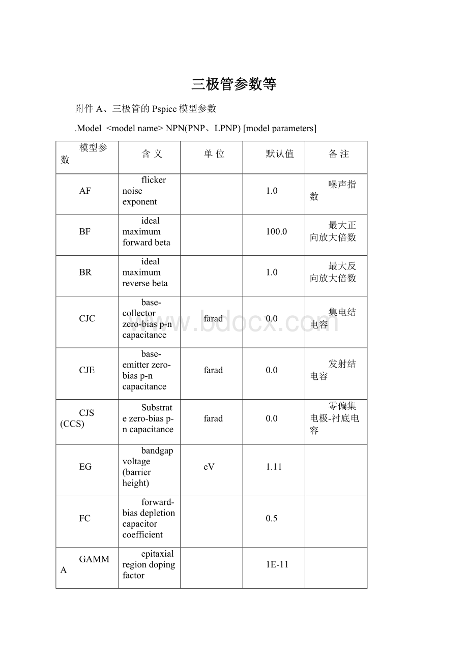
附件A、三极管的Pspice模型参数
.Model NPN(PNP、LPNP)[modelparameters]
模型参数
含义
单位
默认值
备注
AF
flickernoiseexponent
1.0
噪声指数
BF
idealmaximumforwardbeta
100.0
最大正向放大倍数
BR
idealmaximumreversebeta
1.0
最大反向放大倍数
CJC
base-collectorzero-biasp-ncapacitance
farad
0.0
集电结电容
CJE
base-emitterzero-biasp-ncapacitance
farad
0.0
发射结电容
CJS(CCS)
Substratezero-biasp-ncapacitance
farad
0.0
零偏集电极-衬底电容
EG
bandgapvoltage(barrierheight)
eV
1.11
FC
forward-biasdepletioncapacitorcoefficient
0.5
GAMMA
epitaxialregiondopingfactor
1E-11
IKF(IK)
cornerforforward-betahigh-currentroll-off
amp
infinite
IKR
cornerforreverse-betahigh-currentroll-off
amp
infinite
IRB
currentatwhichRbfallshalfwayto
amp
infinite
IS
transportsaturationcurrent
amp
1E-16
饱和电流
ISC(C4)
base-collectorleakagesaturationcurrent
amp
0.0
集电结漏电流
ISE(C2)
base-emitterleakagesaturationcurrent
amp
0.0
发射结漏电流
ISS
substratep-nsaturationcurrent
amp
0.0
ITF
transittimedependencyonIc
amp
0.0
KF
flickernoisecoefficient
0.0
噪声系数
MJC(MC)
base-collectorp-ngradingfactor
0.33
MJE(ME)
base-emitterp-ngradingfactor
0.33
MJS(MS)
substratep-ngradingfactor
0.0
NC
base-collectorleakageemissioncoefficient
2.0
集电结漏电系数
NE
base-emitterleakageemissioncoefficient
1.5
发射结漏电系数
NF
forwardcurrentemissioncoefficient
1.0
正向电流系数
NK
high-currentroll-offcoefficient
0.5
NR
reversecurrentemissioncoefficient
1.0
NS
substratep-nemissioncoefficient
1.0
PTF
excessphase@1/(2π?
TF)Hz
degree
0.0
QCO
epitaxialregionchargefactor
coulomb
0.0
RB
zero-bias(maximum)baseresistance
ohm
0.0
最大基极电阻
RBM
minimumbaseresistance
ohm
RB
最小基极电阻
RC
collectorohmicresistance
ohm
0.0
RCO
epitaxialregionresistance
ohm
0.0
RE
emitterohmicresistance
ohm
0.0
TF
idealforwardtransittime
sec
0.0
正向传递时间
TR
idealreversetransittime
sec
0.0
反向传递时间
TRB1
RBtemperaturecoefficient(linear)
0C-1
0.0
RB的温度系数
TRB2
RBtemperaturecoefficient(quadratic)
0C-2
0.0
TRC1
RCtemperaturecoefficient(linear)
0C-1
0.0
TRC2
RCtemperaturecoefficient(quadratic)
0C-2
0.0
TRE1
REtemperaturecoefficient(linear)
0C-1
0.0
TRE2
REtemperaturecoefficient(quadratic)
0C-2
0.0
TRM1
RBMtemperaturecoefficient(linear)
0C-1
0.0
TRM2
RBMtemperaturecoefficient(quadratic)
0C-2
0.0
T_ABS
absolutetemperature
0C
T_MEASURED
measuredtemperature
0C
T_REL_GLOBAL
relativetocurrenttemperature
0C
T_REL_LOCAL
relativetoAKOmodeltemperature
0C
VAF(VA)
forwardEarlyvoltage
volt
infinite
VAR(VB)
reverseEarlyvoltage
volt
infinite
VJC(PC)
base-collectorbuilt-inpotential
volt
0.75
VJE(PE)
base-emitterbuilt-inpotential
volt
0.75
VJS(PS)
substratep-nbuilt-inpotential
volt
0.75
VO
carriermobilitykneevoltage
volt
10.0
VTF
transittimedependencyonVbc
volt
infinite
XCJC
fractionofCJCconnectedinternallytoRb
1.0
XCJC2
fractionofCJCconnectedinternallytoRb
1.0
XTB
forwardandreversebetatemperaturecoefficient
0.0
正向和反向放大倍数的温度影响系数
XTF
transittimebiasdependencecoefficient
0.0
传递时间系数
XTI(PT)
IStemperatureeffectexponent
3.0
IS的温度影响系数
附件B、PSpiceGoalFunction
特征函数
功能说明
Bandwidth(1,db_level)
计算波形1从最大值下降db_leveldb的波形宽度。
BPBW(1,db_level)
SameasBandwidth(1,db_level)
CenterFreq(1,db_level)
计算波形1从最大值下降db_leveldb的两点的中心频率。
Falltime
(1)
计算波形1的下降时间。
GainMargin(1,2)
计算波形1的相位为-180。
时,波形2的分贝值。
GenFall
(1)
类似于Falltime
(1),但它的下降时间相对的y轴是起点于终点,而不是最大值与最小值。
GenRise
(1)
与GenFall
(1)类似,只是它是上升时间。
HPBW(1,db_level)
查找第一次比最大值低db_leveldb的x坐标。
(上升沿)
LPBW(1,db_level)
与HPBW类似,只是用于下降沿。
Maxr(1,begin-x,end-x)
查找区间的最大值。
Overshoot
(1)
计算最大值与终点之间y轴坐标差与终点值的百分比。
Peak(1,n_occur)
查找第n-occur个峰值点的Y值
Period
(1)
计算波形1的周期。
PhaseMargin(1,2)
查找波形1在0分贝时波形2的相位。
Pulsewidth
(1)
计算波形1的脉冲宽度。
Risetime
(1)
计算波形1的上升时间。
Swingr(1,begin-x,end-x)
计算在指定范围内,波形1的最大值与最小值之差。
TPmW2(1,Period)
XatNthy(1,Y-value,n-occur)
查找波形1上第n-occur个Y-value值时的X坐标值。
XatNthYn(1,Y_value,n_occur)
与XatNthy类似,但它查找的Y值必须在下降沿上。
XatNthYp(1,Y_value,n_occur)
与XatNthy类似,但它查找的Y值必须在上升沿上。
XatNthYpct(1,Y_PCT,n_occur)
查找第n-occur个Y轴值为Y轴范围的Y_pct%时的X轴值。
YatX(1,X_value)
查找X-value值处的Y值。
YatXpct(1,X_pct)
查找X轴值为X轴范围的X_pct%时的Y轴值。
附件CModelingvoltage-controlledandtemperature-dependentresistors
AnalogBehavioralModeling(ABM)canbeusedtomodelanonlinearresistorthroughuseofOhm抯lawandtablesandexpressionswhichdescriberesistance.Herearesomeexamples.
Voltage-controlledresistor
IfaResistancevs.Voltagecurveisavailable,alook-uptablecanbeusedintheABMexpression.Thistablecontains(Voltage,Resistance)pairspickedfrompointsonthecurve.Thevoltageinputisnonlinearlymappedfromthevoltagevaluesinthetabletotheresistancevalues.Linearinterpolationisusedbetweentablevalues.
Let抯saythatpointspickedfromaResistancevs.Voltagecurveare:
Voltage
Resistance
0.5
25
1.0
50
2.0
100
TheABMexpressionforthisisshowninFigure1.
Figure1-Voltagecontrolledresistorusinglook-uptable
Temperature-dependentresistor
Atemperature-dependentresistor(orthermistor)canbemodeledwithalook-uptable,oranexpressioncanbeusedtodescribehowtheresistancevarieswithtemperature.ThedenominatorintheexpressioninFigure2isusedtodescribecommonthermistors.TheTEMPvariableintheexpressionisthesimulationtemperature,inCelsius.ThisisthenconvertedtoKelvinbyadding273.15.Thisstepisnecessarytoavoidadividebyzeroprobleminthedenominator,whenT=0C.
NOTE:
TEMPcanonlybeusedinABMexpressions(E,Gdevices).
Figure3showstheresultsofaDCsweepoftemperaturefrom-40to60C.They-axisshowstheresistanceorV(I1:
-)/1A.
Figure2-Temperaturecontrolledresistor Figure3-PSpiceplotofResistancevs.Temperature(current=1A)
VariableQRLCnetwork
Inmostcircuitsthevalueofaresistorisfixedduringasimulation.WhilethevaluecanbemadetochangeforasetofsimulationsbyusingaParametricSweeptomovethroughafixedsequenceofvalues,avoltage-controlledresistorcanbemadetochangedynamicallyduringasimulation.ThisisillustratedbythecircuitshowninFigure5,whichemploysavoltage-controlledresistor.
Figure4-Parametersweepofcontrolvoltage
Thiscircuitemploysanexternalreferencecomponentthatissensed.Theoutputimpedanceequalsthevalueofthecontrolvoltagetimesthereference.Here,wewilluseRref,a50ohmresistorasourreference.Asaresult,theoutputimpedanceisseenbythecircuitasafloatingresistorequaltothevalueofV(Control)timestheresistancevalueofRref.Inourcircuit,thecontrolvoltagevalueissteppedfrom0.5voltto2voltsin0.5voltsteps,therefore,theresistancebetweennodes3and0variesfrom25ohmsto100ohmsin25ohm-steps.
Figure5-VariableQRLCcircuit Figure6-OutputwaveformsofvariableQRLCcircuit
Atransientanalysisofthiscircuitusinga0.5mswidepulsewillshowhowtheringingdiffersastheQisvaried.
UsingProbe,wecanobservehowtheringingvariesastheresistancechanges.Figure6showstheinputpulseandthevoltageacrossthecapacitorC1.Comparingthefouroutputwaveforms,wecanseethemostpronouncedringingoccurswhentheresistorhasthelowestvalueandtheQisgreatest.Anysignalsourcecanbeusedtodrivethevoltage-controlledresistance.Ifwehadusedasinusoidalcontrolsourceinsteadofastaircase,theresistancewouldhavevarieddynamicallyduringthesimulation.
附件D 变压器PSpice模型
等效电路变压器模型
*TransformerSubcircuitParameters *RATIO=Turnsratio=Secondary/Primary
 升级会员
升级会员 