UniversalBridge模块simulink仿真.docx
《UniversalBridge模块simulink仿真.docx》由会员分享,可在线阅读,更多相关《UniversalBridge模块simulink仿真.docx(11页珍藏版)》请在冰豆网上搜索。
UniversalBridge模块simulink仿真
Universal-Bridge模块simulink仿真
UniversalBridge-Implementuniversalpowerconverterwithselectabletopologiesandpowerelectronicdevices
通用电桥-具有可选择的拓扑结构和电力电子设备的通用电源转换器的实现
Library
PowerElectronics
Description
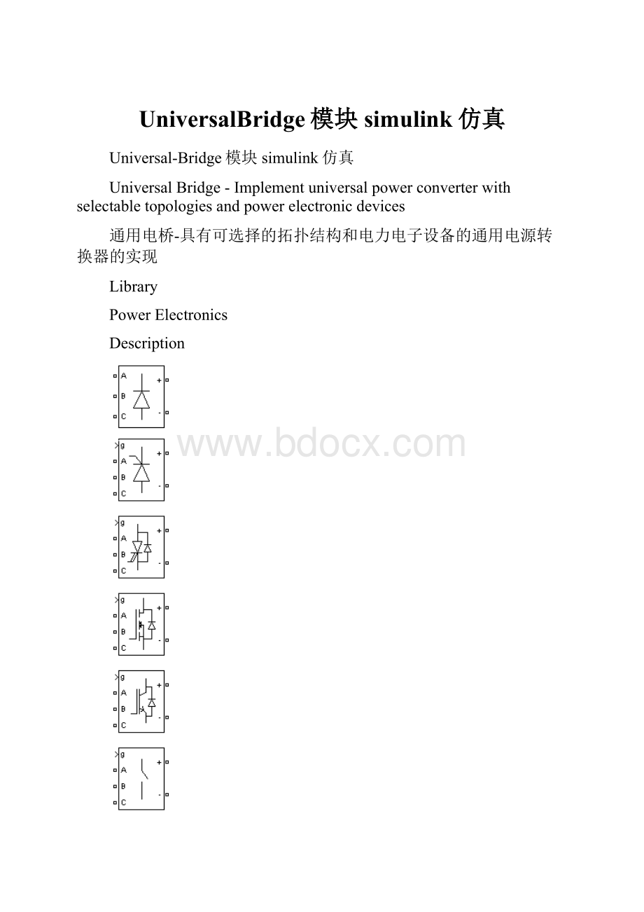
TheUniversalBridgeblockimplementsauniversalthree-phasepowerconverterthatconsistsofuptosixpowerswitchesconnectedinabridgeconfiguration.Thetypeofpowerswitchandconverterconfigurationareselectablefromthedialogbox.
通用电桥模块可以看作一个通用的三相电源转换器,由最高六个电源开关连接在一个桥路中配置。
电源开关和转换器配置类型参数在对话框中选择。
TheUniversalBridgeblockallowssimulationofconvertersusingbothnaturallycommutated(orline-commutated)powerelectronicdevices(diodesorthyristors)andforced-commutateddevices(GTO,IGBT,MOSFET).
通用电桥模块可以仿真自然换流器(或换线)电力电子器件(二极管或晶闸管)
nominalcurrentwhenpowerelectronicdevicesarenotconducting.
当电力电子器件是不导电时,基波频率下的缓冲泄漏电流小于额定电流的0.1%
TheRCtimeconstantofsnubbersishigherthantwotimesthesampletimeTs.
TheseRsandCsvaluesthatguaranteenumericalstabilityofthediscretizedbridgecanbedifferentfromactualvaluesusedinaphysicalcircuit.
缓冲电路的RC时间常数大于两倍的采样时间的。
Rs和Cs的值,保证离散化的桥电桥的数值稳定性可以不同的与物理电路中使用的实际值。
Powerelectronicdevice
Selectthetypeofpowerelectronicdevicetouseinthebridge.
选择在电桥中使用的电力电子装置的类型。
WhenyouselectSwitching-functionbasedVSC,aswitching-functionvoltagesourceconvertertypeequivalentmodelisused,whereswitchesarereplacedbytwovoltagesourcesontheACsideandacurrentsourceontheDCside.Thismodelusesthesamefiringpulsesasforotherpowerelectronicdevicesanditcorrectlyrepresentsharmonicsnormallygeneratedbythebridge.
当你选择切换功能的VSC(变压设备),开关功能的电压源整流器型等效模型,其中开关是由两个交流侧电压源和直流源的电流代替的。
该模型使用与其他电力电子设备相同的发射脉冲,它正确地反映正常产生的电桥谐波。
WhenyouselectAverage-modelbasedVSC,anaverage-modeltypeofvoltagesourceconverterisusedtorepresentthepower-electronicswitches.Unliketheotherpowerelectronicdevices,thismodelusesthereferencesignals(uref)representingtheaveragevoltagesgeneratedattheABCterminalsofthebridge.Thismodeldoesnotrepresentharmonics.Itcanbeusedwithlargersampletimeswhilepreservingtheaveragevoltagedynamics.
当你选择基于VSC的平均模型、电压源变换器的平均模型类型是用来表示电力电子开关。
不像其他的电力电子设备,这个模型使用的参考信号(Uref)代表在桥的ABC终端产生的平均电压。
这个模型不代表谐波。
它可以使用更大的样本时间,而公关eserving平均电压动态。
Seethepower_sfavgdemoforanexamplecomparingthesetwomodelstoanUniversalBridgeblockusingIGBT/Diodedevice.
对两个模型的一种通用桥块采用IGBT/二极管器件。
Ron
Internalresistanceoftheselecteddevice,inohms(Ω).
Lon
Internalinductance,inhenries(H),forthediodeorthethyristordevice.Whenthebridgeisdiscretized,theLonparametermustbesettozero.
内部电感,用(H),该二极管或晶闸管装置。
当桥梁离散,LON参数必须设置为零。
ForwardvoltageVf
ThisparameterisavailableonlywhentheselectedPowerelectronicdeviceisDiodesorThyristors.
此参数仅当选定的电力电子器件是二极管或晶闸管可用。
Forwardvoltage,involts(V),acrossthedevicewhenitisconducting.
正向电压,在伏(V),穿过设备时,它正在进行。
Forwardvoltages[DeviceVf,DiodeVfd]
ThisparameterisavailablewhentheselectedPowerelectronicdeviceisGTO/DiodesorIGBT/Diodes.
该参数可选择的电力电子装置是当GTO或IGBT/二极管/二极管。
Forwardvoltages,involts(V),oftheforced-commutateddevices(GTO,MOSFET,orIGBT)andoftheantiparalleldiodes.
[Tf(s)Tt(s)]
FalltimeTfandtailtimeTt,inseconds(s),fortheGTOortheIGBTdevices.
下降时间tf和尾时间TT,秒(s),对GTO或IGBT器件来说
Measurements
SelectDevicevoltagestomeasurethevoltagesacrossthesixpowerelectronicdeviceterminals.
选择设备电压测量的六个电力电子设备终端的电压。
SelectDevicecurrentstomeasurethecurrentsflowingthroughthesixpowerelectronicdevices.Ifantiparalleldiodesareused,themeasuredcurrentisthetotalcurrentintheforced-commutateddevice(GTO,MOSFET,orIGBT)andintheantiparalleldiode.Apositivecurrentthereforeindicatesacurrentflowingintheforced-commutateddeviceandanegativecurrentindicatesacurrentflowinginthediode.Ifsnubberdevicesaredefined,themeasuredcurrentsaretheonesflowingthroughthepowerelectronicdevicesonly.
选择设备电流来测量流经六个电力电子设备的电流。
如果用反并联二极管,测量电流在强迫换相开发的总电流冰(GTO,MOSFET,或IGBT)在反平行二极管。
正电流因此显示当前在强制换向装置和负电流表示电流二极管。
如果定义了缓冲装置,测量电流的流经电力电子器件只。
SelectUABUBCUCAUDCvoltagestomeasuretheterminalvoltages(ACandDC)oftheUniversalBridgeblock.
选择UABUBCUCAUDC电压测量端电压(ACDC)的通用桥块。
SelectAllvoltagesandcurrentstomeasureallvoltagesandcurrentsdefinedfortheUniversalBridgeblock.
选择所有的电压和电流来测量所有的电压和电流定义为通用桥块。
PlaceaMultimeterblockinyourmodeltodisplaytheselectedmeasurementsduringthesimulation.IntheAvailableMeasurementsmenuoftheMultimeterblock,themeasurementisidentifiedbyalabelfollowedbytheblockname.
将万用表的块中的模型显示在选定的测量仿真。
在万用表的块可用的测量菜单,测量的标签标识其次是块名。
Measurement
Label
Devicevoltages
Usw1:
Usw2:
Usw3:
Usw4:
Usw5:
Usw6:
Branchcurrent
Isw1:
Isw2:
Isw3:
Isw4:
Isw5:
Isw6:
Terminalvoltages
Uab:
Ubc:
Uca:
Udc:
InputsandOutputs
Thegateinputforthecontrolledswitchdevices.ThepulseorderinginthevectorofthegatesignalscorrespondstotheswitchnumberindicatedinthesixcircuitsshownintheDescriptionsection.Forthediodeandthyristorbridges,thepulseorderingcorrespondstothenaturalorderofcommutation.Forallotherforced-commutatedswitches,pulsesaresenttoupperandlowerswitchesofphasesA,B,andC.
用于控制开关器件的栅极输入。
在栅极信号的矢量中的脉冲顺序对应于在描述部分中显示的六个电路中表示的开关数。
对于二极管和晶闸管桥,脉冲顺序对应于换向的自然顺序。
对于所有其他强制换向开关,脉冲发送到上下开关相A、B和C
Topology
PulseVectorofInputg
onearm
[Q1,Q2]
twoarms
[Q1,Q2,Q3,Q4]
threearms
[Q1,Q2,Q3,Q4,Q5,Q6]
Example
Thepower_bridgesdemoillustratestheuseoftwoUniversalBridgeblocksinanac/dc/acconverterconsistingofarectifierfeedinganIGBTinverterthroughaDClink.Theinverterispulse-widthmodulated(PWM)toproduceathree-phase50Hzsinusoidalvoltagetotheload.Inthisexampletheinverterchoppingfrequencyis2000Hz.
power_bridges案例-在交流/直流/交流转换器包括一个整流器供给IGBT逆变器通过直流环节两通用桥式块的使用。
该逆变器是脉冲宽度国防部调节(PWM)产生三相50赫兹的正弦电压的负载。
在这个例子中,逆变器的斩波频率为2000赫兹。
TheIGBTinverteriscontrolledwithaPIregulatorinordertomaintaina1puvoltage(380Vrms,50Hz)attheloadterminals.
IGBT逆变器是一个以PI调节器保持1的PU电压控制(380Vrms,50Hz)的终端负载。
AMultimeterblockisusedtoobservecommutationofcurrentsbetweendiodes1and3inthediodebridgeandbetweenIGBT/Diodesswitches1and2intheIGBTbridge.
万用表块是用来观察二极管1和3之间的电流换向二极管桥和IGBT/二极管开关1和2在IGBT桥之间。
Startsimulation.Afteratransientperiodofapproximately40ms,thesystemreachesasteadystate.ObservevoltagewaveformsatDCbus,inverteroutput,andloadonScope1.Theharmonicsgeneratedbytheinverteraroundmultiplesof2kHzarefilteredbytheLCfilter.Asexpectedthepeakvalueoftheloadvoltageis537V(380VRMS).
启动仿真。
经过约40毫秒的瞬态期间,该系统达到一个稳定的状态。
观察在直流母线电压波形和负载,逆变器输出,一级。
谐波的产生由逆变器的2千赫的倍数的倍数的滤波器的LC滤波器。
正如预期的负载电压的峰值为537V(380V的有效值)。
Insteadystatethemeanvalueofthemodulationindexism=0.8,andthemeanvalueoftheDCvoltageis778V.Thefundamentalcomponentof50Hzvoltageburiedinthechoppedinvertervoltageistherefore
在稳态的调制指数的平均值为M=0.8,和直流电压的平均值为778V。
50赫兹的电压埋在斩波逆变器电压的基本组成部分是
Vab=778V*0.612*0.80=381VRMS
Observediodecurrentsontrace1ofScope2,showingcommutationfromdiode1todiode3.Alsoobserveontrace2currentsinswitches1and2oftheIGBT/Diodebridge(upperandlowerswitchesconnectedtophaseA).Thesetwocurrentsarecomplementary.ApositivecurrentindicatesacurrentflowingintheIGBT,whereasanegativecurrentindicatesacurrentflowingintheantiparalleldiode.
观察1种适用范围2二极管电流,显示从1到3的二极管整流二极管。
同时观察微量2电流开关1和2的IGBT/二极管桥(上部和下部的开关连接A相A)。
这两个电流是互补的。
正电流指示电流IGBT中的流动,而负电流表示电流在反向并联二极管流动。
 升级会员
升级会员 