思科模拟器实训.docx
《思科模拟器实训.docx》由会员分享,可在线阅读,更多相关《思科模拟器实训.docx(19页珍藏版)》请在冰豆网上搜索。
思科模拟器实训
实验一:
交换机的基本配置与Telnet远程登陆配置
实验目标:
掌握交换机的基本配置Telnet远程登陆配置
实验项目:
一公司新近一批交换机,再投入网络使用后要进行一些配置和管理,作为网络管理员请你给你初始配置:
并支持远程登录管理(Telnet远程登陆配置)
>用户模式
#特权模式
(conf)#全局模式
(conf-if)#端口模式
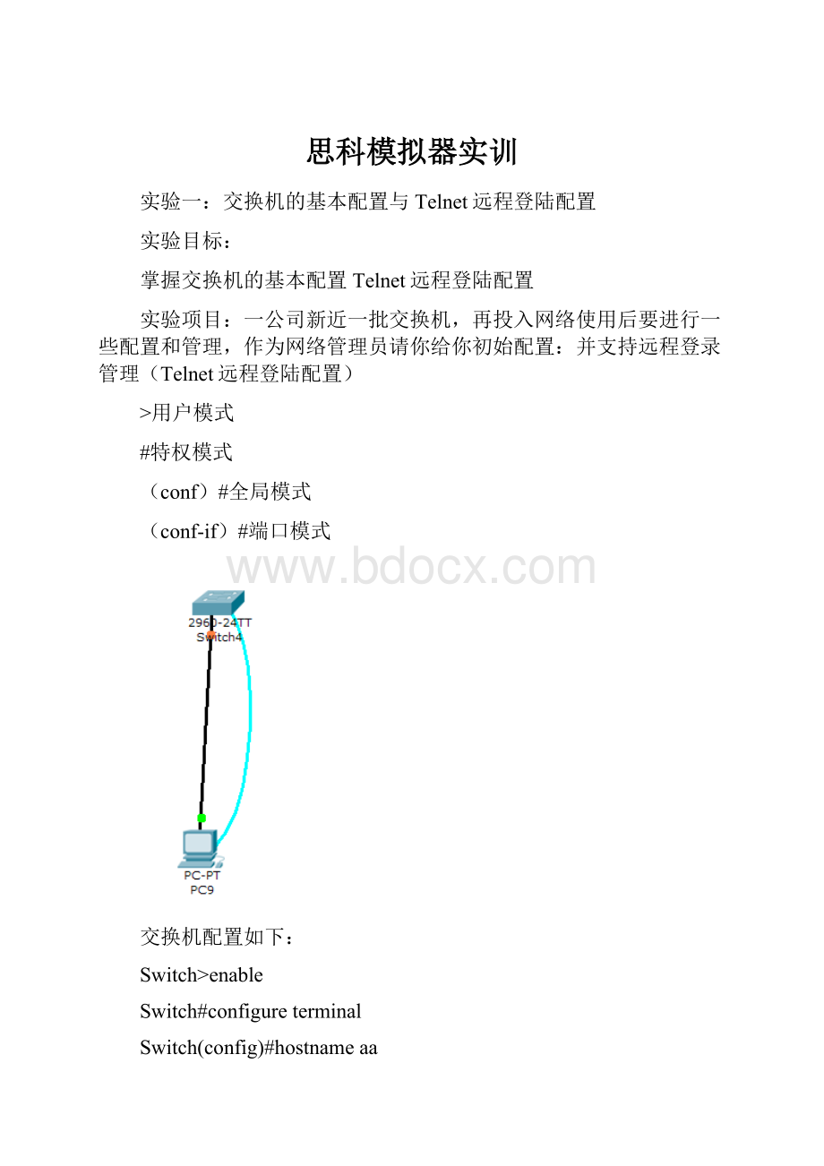
交换机配置如下:
Switch>enable
Switch#configureterminal
Switch(config)#hostnameaa
aa(config)#enablepassword123
aa(config)#exit
aa#configureterminal
Enterconfigurationcommands,oneperline.EndwithCNTL/Z.
aa(config)#linevty04
aa(config-line)#password123456
aa(config-line)#login
aa(config-line)#exit
aa(config)#vlan1
aa(config-vlan)#exit
aa(config)#interfacevlan1
aa(config-if)#ipadd
aa(config-if)#ipaddress192.168.1.100255.255.255.0
aa(config-if)#noshutdown
aa(config-if)#exit
aa(config)#interfaceFastEthernet0/1
aa(config-if)#
aa(config-if)#exit
aa(config)#ipdefault-gateway192.168.1.1
aa(config)#end
aa#exit
设置计算机ip地址为:
192.168.1.100网管:
192.168.1.1
实验结果:
用命令实现以下操作:
1.查看本机ip地址
2.Ping交换机地址
3.Ping网关地址
4.Ping本机地址
5.远程登录交换机查看交换机运行信息
实验二:
交换机划分vlan设置
实验目标:
交换机划分vlan设置
实验项目:
某公司财务部和销售部的计算机通过两台交换机实现通讯,要求财务部和销售部内部的计算机可以互通,但为了安全期间要求财务部和销售部进行安全隔离,请做配置
1.单个交换机划分vlan
Switch>enable
Switch#configuret
Switch#configureterminal
Enterconfigurationcommands,oneperline.EndwithCNTL/Z.
Switch(config)#h
Switch(config)#hostnameaa
aa(config)#vlan1
aa(config-vlan)#exit
aa(config)#interfacevlan1
aa(config-if)#ipaddress192.168.1.100255.255.255.0
aa(config-if)#noshutdown
aa(config-if)#exit
aa(config)#ipdefault-gateway192.168.1.1
aa(config)#vlan10
aa(config-vlan)#exit
aa(config)#vlan20
aa(config-vlan)#exit
aa(config)#interfacerangefastEthernet0/1-12
aa(config-if-range)#switchportaccessvlan10
aa(config-if-range)#exit
aa(config)#interfacerangefastEthernet0/13-24
aa(config-if-range)#switchportaccessvlan20
aa(config-if-range)#exit
aa(config)#exit
aa#
实验结果:
用命令实现以下操作:
1,pc1ip地址192.168.1.224网管:
192.168.1.1端口接1-12
2,pc2ip地址192.168.1.324网管:
192.168.1.1端口接13-24
3,pc3ip地址192.168.1.424网管:
192.168.1.1端口接1-12
4,pc4ip地址192.168.1.524网管:
192.168.1.1端口接13-24
5,四台pc机相互ping
6,Ping交换机地址
2.多交换机划分vlan两台交换机配置一样
Switch>enable
Switch#configureterminal
Enterconfigurationcommands,oneperline.EndwithCNTL/Z.
Switch(config)#hostnameaa
aa(config)#vlan2
aa(config-vlan)#exit
aa(config)#vlan3
aa(config-vlan)#exit
aa(config)#interfacef
aa(config)#interfacefastEthernet0/1
aa(config-if)#switchportaccessvlan2
aa(config-if)#exit
aa(config)#interfacefastEthernet0/2
aa(config-if)#switchportaccessvlan3
aa(config-if)#exit
aa(config)#interfacefastEthernet0/24
aa(config-if)#switchportmodetrunk
aa(config-if)#exit
aa(config)#interfacevlan1
aa(config-if)#ipaddress192.168.1.100255.255.255.0
aa(config-if)#noshutdown
aa(config-if)#exit
aa(config)#ipdefault-gateway192.168.1.1
aa(config)#exit
aa#
实验结果:
用命令实现以下操作:
1,pc1ip地址192.168.1.224网管:
192.168.1.1端口接1
2,pc2ip地址192.168.1.324网管:
192.168.1.1端口接2
3,pc3ip地址192.168.1.424网管:
192.168.1.1端口接1
4,pc4ip地址192.168.1.524网管:
192.168.1.1端口接2
5,四台pc机相互ping
6,Ping交换机地址
实验三:
不同vlan之间的通讯
一、实验目的
1、理解多层交换机的路由原理
2、了解多层交换机在实际网络中的常用配置
3、回顾二层交换机VLAN的划分方法
4、进一步理解802.1Q的原理和使用方法
二、应用环境
二层交换机属于接入层交换机,在二层交换机上根据连接用户的不同,划分了不同
VLAN,有时候会出现同一个VLAN处于不同的交换机上。
这些二层交换机被一台三层交
换机所汇聚。
因此我们需要实现多交换机的跨交换机VLAN通信,也需要实现VLAN间的
通信。
因此出现本实验所要演示的功能。
三、实验设备
1、DCRS-7604(或6804或5526S)交换机1台
2、DCS-3926S交换机1-2台
3、PC机2-4台
4、Console线1-3根
5、直通网线若干
四、实验拓扑
五、实验要求
在交换机A和交换机B上分别划分两个基于端口的VLAN:
VLAN100,VLAN200。
VLAN
100
200
Trunk口
端口成员
1~8
9~16
24
在交换机C上也划分两个基于端口的VLAN:
VLAN100,VLAN200。
把端口1和端口
2都设置成Trunk口。
VLAN
100
200
Trunk口
IP
192.168.10.1
192.168.20.1
Mask
255.255.255.0
255.255.255.0
1/1和1/2
交换机A的24口连接交换机C的1口,交换机B的24口连接交换机C的2口。
PC1-PC4的网络设置为:
设备
IP地址
gateway
Mask
PC1192.168.10.11
PC2192.168.20.22
192.168.10.1
192.168.20.1
255.255.255.0
255.255.255.0
PC3
192.168.10.33
192.168.10.1
255.255.255.0
验证:
PC4192.168.20.44
192.168.20.1
255.255.255.0
1、不给PC设置网关:
PC1、PC3分别接在不同交换机VLAN100的成员端口1~8上,两台PC互相可以ping
通;PC2、PC4分别接在不同交换机VLAN的成员端口9~16上,两台PC互相可以ping通;
PC1、PC3和PC2、PC4接在不同VLAN的成员端口上则互相ping不通。
2、给PC设置网关:
PC1、PC3和PC2、PC4接在不同VLAN的成员端口上也可以互相ping通。
若实验结果和理论相符,则本实验完成。
六、实验步骤
第一步:
交换机恢复出厂设置
switch#setdefault
switch#write
switch#reload
第二步:
给交换机设置标示符和管理IP。
交换机A:
switch(Config)#hostnameswitchA
switchA(Config)#interfacevlan1
switchA(Config-If-Vlan1)#ipaddress192.168.1.11255.255.255.0
switchA(Config-If-Vlan1)#noshutdown
switchA(Config-If-Vlan1)#exit
switchA(Config)#
交换机B:
switch(Config)#hostnameswitchB
switchB(Config)#interfacevlan1
switchB(Config-If-Vlan1)#ipaddress192.168.1.12255.255.255.0
switchB(Config-If-Vlan1)#noshutdown
switchB(Config-If-Vlan1)#exit
switchB(Config)#
交换机C:
DCRS-7604#config
DCRS-7604(Config)#
DCRS-7604(Config)#hostnameswitchC
switchC(Config)#interfacevlan1
switchC(Config-If-Vlan1)#ipaddress192.168.1.13255.255.255.0
switchC(Config-If-Vlan1)#noshutdown
switchC(Config-If-Vlan1)#exit
switchC(Config)#exit
switchC#
第三步:
在交换机中创建vlan100和vlan200,并添加端口。
交换机A:
switchA(Config)#vlan100
switchA(Config-Vlan100)#
switchA(Config-Vlan100)#switchportinterfaceethernet0/0/1-8
switchA(Config-Vlan100)#exit
switchA(Config)#vlan200
switchA(Config-Vlan200)#switchportinterfaceethernet0/0/9-16
switchA(Config-Vlan200)#exit
switchA(Config)#
验证配置:
switchA#showvlan
VLANNameTypeMediaPorts
--------------------------------------------------------------------------
1defaultStaticENETEthernet0/0/17Ethernet0/0/18
Ethernet0/0/19Ethernet0/0/20
Ethernet0/0/21Ethernet0/0/22
Ethernet0/0/23Ethernet0/0/24
100VLAN0100StaticENETEthernet0/0/1Ethernet0/0/2
Ethernet0/0/3Ethernet0/0/4
Ethernet0/0/5Ethernet0/0/6
Ethernet0/0/7Ethernet0/0/8
200VLAN0200StaticENETEthernet0/0/9Ethernet0/0/10
Ethernet0/0/11Ethernet0/0/12
Ethernet0/0/13Ethernet0/0/14
Ethernet0/0/15Ethernet0/0/16
switchA#
交换机B:
配置与交换机A一样。
第四步:
设置交换机trunk端口
交换机A:
switchA(Config)#interfaceethernet0/0/24
switchA(Config-Ethernet0/0/24)#switchportmodetrunk
SettheportEthernet0/0/24modeTRUNKsuccessfully
switchA(Config-Ethernet0/0/24)#switchporttrunkallowedvlanall
settheportEthernet0/0/24allowedvlansuccessfully
switchA(Config-Ethernet0/0/24)#exit
switchA(Config)#
验证配置:
switchA#showvlan
VLANNameTypeMediaPorts
--------------------------
----------------------------------------
---------
1defaultStaticENETEthernet0/0/17Ethernet0/0/18
Ethernet0/0/19Ethernet0/0/20
Ethernet0/0/21Ethernet0/0/22
Ethernet0/0/23
Ethernet0/0/24(T)
100VLAN0100StaticENETEthernet0/0/1Ethernet0/0/2
Ethernet0/0/3Ethernet0/0/4
Ethernet0/0/5Ethernet0/0/6
Ethernet0/0/7Ethernet0/0/8
Ethernet0/0/24(T)
200VLAN0200StaticENETEthernet0/0/9Ethernet0/0/10
Ethernet0/0/11Ethernet0/0/12
Ethernet0/0/13Ethernet0/0/14
Ethernet0/0/15Ethernet0/0/16
Ethernet0/0/24(T)
switchA#
24口已经出现在vlan1、vlan100和vlan200中,并且24口不是一个普通端口,是tagged
端口。
交换机B:
配置同交换机A
交换机C:
switchC(Config)#vlan100
switchC(Config-Vlan100)#exit
switchC(Config)#vlan200
switchC(Config-Vlan200)#exit
switchC(Config)#interfaceethernet1/1-2
switchC(Config-Port-Range)#switchportmodetrunk
SettheportEthernet1/1modeTRUNKsuccessfully
SettheportEthernet1/2modeTRUNKsuccessfully
switchC(Config-Port-Range)#switchporttrunkallowedvlanall
settheportEthernet1/1allowedvlansuccessfully
settheportEthernet1/2allowedvlansuccessfully
switchC(Config-Port-Range)#exit
switchC(Config)#exit
验证配置:
switchC#showvlan
VLANNameTypeMediaPorts
---------------------------------------------------------------------------
1defaultStaticENETEthernet1/1(T)Ethernet1/2(T)
Ethernet1/3Ethernet1/4
Ethernet1/5Ethernet1/6
Ethernet1/7Ethernet1/8
Ethernet1/9Ethernet1/10
Ethernet1/11Ethernet1/12
Ethernet1/13Ethernet1/14
Ethernet1/15Ethernet1/16
Ethernet1/17Ethernet1/18
Ethernet1/19Ethernet1/20
Ethernet1/21Ethernet1/22
Ethernet1/23Ethernet1/24
Ethernet1/25Ethernet1/26
Ethernet1/27Ethernet1/28
100VLAN0100StaticENETEthernet1/1(T)Ethernet1/2(T)
200VLAN0200StaticENETEthernet1/1(T)Ethernet1/2(T)
switchC#
第五步:
交换机C添加vlan地址。
switchC(Config)#interfacevlan100
switchC(Config-If-Vlan100)#ipaddress192.168.10.1255.255.255.0
switchC(Config-If-Vlan100)#noshut
switchC(Config-If-Vlan100)#exit
switchC(Config)#interfacevlan200
switchC(Config-If-Vlan200)#noshutdown
switchC(Config-If-Vlan200)#exit
switchC(Config)#
验证配置:
switch#showiproute
Totalrouteitemsis3,thematchedrouteitemsis3
Codes:
C-connected,S-static,R-RIPderived,O-OSPFderived
A-OSPFASE,B-BGPderived,D-DVMRPderived
DestinationMaskNexthopInterfacePreference
C192.168.1.0255.255.255.00.0.0.0Vlan10
C192.168.10.0255.255.255.00.0.0.0Vlan1000
C192.168.20.0255.255.255.00.0.0.0Vlan2000
switch#
第七步:
验证实验。
1、PC不配置网关,互相ping,查看结果;
2、PC配置网关,互相ping,查看结果;
七、注意事项和排错
Showiproute的时候,如果在某一个网段上没有active的设备连接在三层交换机上,
则这个网段的路由不会被显示出来。
八、配置序列
略
九、共同思考
如果两台三层交换机级联,如何进行vlan的配置?
需要把某些端口的模式设置为trunk
么?
十、课后练习
在交换机A和交换机B上分别划分两个基于端口的VLAN:
VLAN10,VLAN20。
VLAN
10
20
Trunk口
端口成员
2~4
5~8
1
在交换机C上也划分两个基于端口的VLAN:
VLAN10,VLAN20。
把端口1和端口2
都设置成Trunk口。
VLAN
10
20
Trunk口
IP
10.1.10.1
10.1.20.1
Mask
255.255.255.0
255.255.255.0
1/1和1/2
交换机A的1口连接交换机C的1口,交换机B的1口连接交换机C的2口。
PC的网络设置为:
设备
端口
IP地址
gateway
Mask
PC1switchA2口
PC2SwitchB8口
10.1.10.11
10.1.20.22
10.1.10.1
10.1.20.1
255.255.255.0
255.2
 升级会员
升级会员 