packettracer510全攻略下.docx
《packettracer510全攻略下.docx》由会员分享,可在线阅读,更多相关《packettracer510全攻略下.docx(81页珍藏版)》请在冰豆网上搜索。
packettracer510全攻略下
十、配置单区域OSPF
OSPF(OpenShortestPathFirst开放式最短路径优先)是一个内部网关协议(InteriorGatewayProtocol,简称IGP),用于在单一自治系统(autonomoussystem,AS)内决策路由。
OSPF协议比较复杂Fversion2RFC2328标准文档长达224页,可以划分区域是OSPF能多适应大型复杂网络的一个特性,我们只借助完成单个area的简单配置。
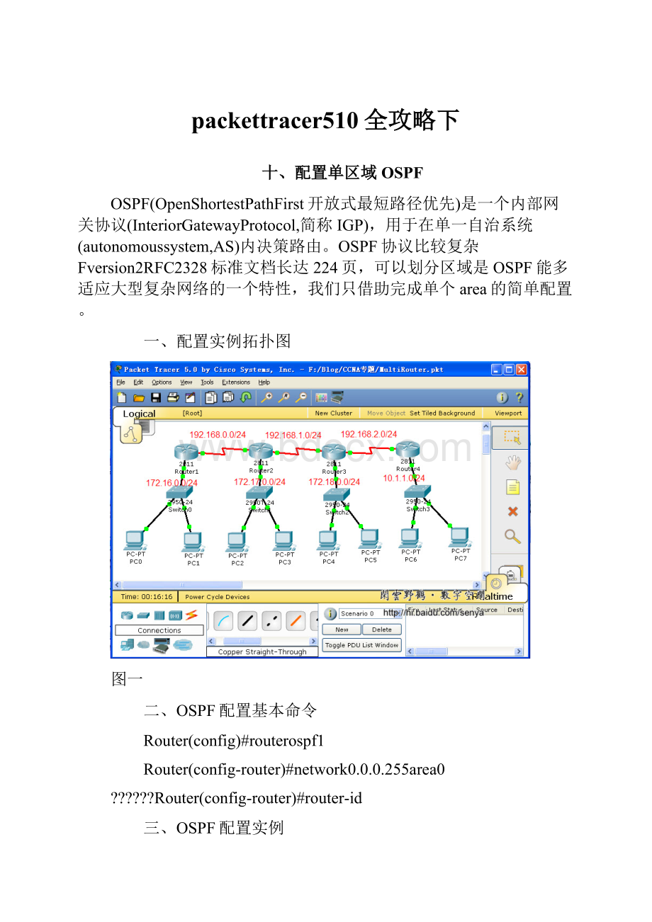
一、配置实例拓扑图
图一
二、OSPF配置基本命令
Router(config)#routerospf1
Router(config-router)#network0.0.0.255area0
?
?
?
?
?
?
Router(config-router)#router-id
三、OSPF配置实例
1、路由器基本配置
图二 以Router1为例介绍网络中各个路由器的基本配置
2、启动OSPF
图三
图四?
?
Router1的OSPF配置
图五?
?
Router2的OSPF配置
图六?
?
Router3的OSPF配置
图七?
?
Router4的OSPF配置
图八 查看路由器中的路由表
3、校验、诊断
图九 showipprotocol查看路由器中所启用的路由计算协议
图十 showipospf
图十一 showipospfinterface
图十二
图十三 showipospfneighbor 想看邻居
图十四 showipospfdatabase
图十五 debugipospfevents开启诊断,nodebugipospfevents关闭诊断
图十六 pc2ping通所有网段内的计算机或路由器
在这里只能进行最为简单的OSPF配置了,可以完成CCNA的实验。
十一、路由器实现Vlan间通信
一、实验拓扑图
图一 路由器:
Cisco2811,交换机:
Cisco2950
二、创建Vlan
2950#vlandatabae
2950(vlan)#vlan10namemath
2950(vlan)#vlan20namechinese
图二
三、把交换机端口分配给Vlan
2950#conft
2950(config)#intrangefa0/2-3
2950(config-if-range)#switchportmodeaccess
2950(config-if-range)#switchportaccessvlan10
2950(config-if-range)#intrangefa0/4-5
2950(config-if-range)#switchportmodeaccess
2950(config-if-range)#switchportaccessvlan20
图三
四、配置交换机trunk端口
2950(config)intfa0/1
2950(config-if)switchportmodetrunk
图四
五、配置路由器子接口
Router#conft
Router(config)#intfa0/1.1
Router(config-subif)#encapsulationdot1q10
Router(config-subif)#ipaddress
Router(config-subif)#intfa0/1.2
Router(config-subif)#encapsulationdot1q20
Router(config-subif)#ipaddress
Router(config-subif)#intfa0/1
Router(config-if)#noshut
图五
图六 查看路由器中的路由表
六、配置计算机,测试
在本次实验中,pc0与pc1同处于vlan1020
图七 不同网段中的计算机完全可以ping通
十二、PPP
PPP(PointtoPointProtocol)数据链路层协议。
两种认证方式:
一种是PAP,一种是CHAP。
相对来说PAP的认证方式安全性没有CHAP高。
PAP在传输password是明文的,而CHAP在传输过程中不传输密码,PAP认证是通过两次握手实现的,而CHAP则是通过3次握手实现的。
一、实验配置拓扑图
图一
二、PPP的基本配置命令
Router(config-if)#encapsulationPPP
Router(config-if)#PPPmultilink
Router(config-if)#PPPauthenticationchap
三、配置PPP
图二 路由器Boson上配置PPP的命令
图三?
?
Newyork上配置PPP的命令
图四 启用RIP路由协议,两个路由器要配置RIP
Boson路由器的配置:
Boston#shrunning-config
Buildingconfiguration...
Currentconfiguration:
652bytes
!
version12.4
noservicepassword-encryption
!
hostnameBoston
!
!
!
!
!
usernameNewyorkpassword0senya
!
ipsshversion1
noipdomain-lookup
!
!
interfaceFastEthernet0/0
noipaddress
duplexauto
speedauto
shutdown
!
interfaceFastEthernet0/1
ipaddress
duplexauto
speedauto
!
interfaceSerial0/3/0
descriptionLinktoRouterNewyork
ipaddress
encapsulationppp
pppauthenticationchap
clockrate56000
!
interfaceVlan1
noipaddress
shutdown
!
routerrip
version2
network
network
!
ipclassless
!
!
!
!
!
linecon0
linevty04
login
!
!
end
Newyork路由器的配置:
Newyork#shrunning-config
Buildingconfiguration...
Currentconfiguration:
606bytes
!
version12.4
noservicepassword-encryption
!
hostnameNewyork
!
!
!
!
!
usernameBostonpassword0senya
!
ipsshversion1
!
!
interfaceFastEthernet0/0
noipaddress
duplexauto
speedauto
shutdown
!
interfaceFastEthernet0/1
ipaddress
duplexauto
speedauto
!
interfaceSerial0/3/0
descriptionlinktoBoston
ipaddress
encapsulationppp
pppauthenticationchap
!
interfaceVlan1
noipaddress
shutdown
!
routerrip
version2
network
network
!
ipclassless
!
!
!
!
!
linecon0
linevty04
login
!
!
end
图五 配置计算机的IP地址及网关
图六 在计算机PC0上使用ping命令检查网络的连通性
十三、帧中继FrameRelay
帧中继是一种用于连接计算机系统的面向分组的通信方法。
它主要用在公共或专用网上的局域网互联以及广域网连接。
大多数公共电信局都提供帧中继服务,把它作为建立高性能的虚拟广域连接的一种途径。
帧中继是进入带宽范围从56Kbps到1.544Mbps的广域分组交换网的用户接口。
帧中继是从综合业务数字网中发展起来的,并在1984年推荐为国际电话电报咨询委员会(CCITT)的一项标准,另外,由美国国家标准协会授权的美国TIS标准委员会也对帧中继做了一些初步工作。
数据链路连接标识符(DLCI)这个信息包含标识号,它标识多路复用到通道的逻辑连结。
帧中继交换机将两端的DLCI关联起来,它是帧中继帧格式中地字段的一个重要部分之一,这是个6位标识,表示正在进行的客户和服务器之间的连接,用于RFCOMM层。
帧中继使用DLCI来标识DTE和服务商交换机之间的虚电路。
DLCI字段的长度一般为10bit,但也可扩展为16bit,前者用二字节地址字段,后者是三字节地址字段。
23bit用四字节地址字段。
DLCI值用于标识永久虚电路(PVC),呼叫控制或管理信息。
DLCI只具有本地意义。
一、使用PacketTracer5.0构建帧中继仿真
添加三个2811路由器和一个云
图一
图二 给2811添加一个具有串口的模块
图三
图四 把路由器2811的串口与云的串口相连,路由器的串口为DTE
图五 实验拓扑图及IP地址、DLCI分配
二、配置FrameRelay
以Router2为例,其它两个路由器相似,\\后是人为添加的注释,在实际配置时不存在
Router>en \\进入特权配置模式
Router#conft \\进入全局配置模式
Enterconfigurationcommands,oneperline.EndwithCNTL/Z.
Router(config)#noipdomain-lookup \\取消名称解析
Router(config)#hostnameRouter2 \\配置路由器的名字
Router2(config)#intfa0/1 \\进入接口配置模式
Router2(config-if)#ipaddress
Router2(config-if)#noshut \\激活端口
%LINK-5-CHANGED:
InterfaceFastEthernet0/1,changedstatetoup
%LINEPROTO-5-UPDOWN:
LineprotocolonInterfaceFastEthernet0/1,changedstatetoup
Router2(config-if)#intserial0/3/0
Router2(config-if)#encapsulationframe-relay \\对串口serial0/3/0进行frame-relay封装
Router2(config-if)#noshut
%LINK-5-CHANGED:
InterfaceSerial0/3/0,changedstatetoup
Router2(config-if)#
%LINEPROTO-5-UPDOWN:
LineprotocolonInterfaceSerial0/3/0,changedstatetoup
Router2(config-if)#interfaceserial0/3/0.1point-to-point \\进入串口的子接口配置模式
%LINK-5-CHANGED:
InterfaceSerial0/3/0.1,changedstatetoup
%LINEPROTO-5-UPDOWN:
LineprotocolonInterfaceSerial0/3/0.1,changedstatetoupRouter2
(config-subif)#ipaddress\\为子接口配置IP地址
Router2(config-subif)#descriptionLinkRouter1DLCI30 \\为子接口添加描述
Router2(config-subif)#frame-relayinterface-dlci40 \\配置DLCI
Router2(config-subif)#interfaceserial0/3/0.2point-to-point
%LINK-5-CHANGED:
InterfaceSerial0/3/0.2,changedstatetoup
%LINEPROTO-5-UPDOWN:
LineprotocolonInterfaceSerial0/3/0.2,changedstatetoupRouter2
(config-subif)#ipaddress
Router2(config-subif)#descriptionlinktoRouter0DLCI20
Router2(config-subif)#frame-relayinterface-dlci41
Router2(config-subif)#end
%SYS-5-CONFIG_I:
Configuredfromconsolebyconsole
Router2#conft
Enterconfigurationcommands,oneperline.EndwithCNTL/Z.
Router2(config)#routereigrp100 \\在路由器上启用EIGRP路由协议
Router2(config-router)#network
Router2(config-router)#network
Router2(config-router)#network
Router2(config-router)#
%SYS-5-CONFIG_I:
Configuredfromconsolebyconsole
Router2#copyrunning-configstartup-config \\保存配置
Destinationfilename[startup-config]?
Buildingconfiguration...
[OK]
Router2#
路由器Router0的配置:
Router0#shrunning-config
Buildingconfiguration...
Currentconfiguration:
830bytes
!
version12.4
noservicepassword-encryption
!
hostnameRouter0
!
!
!
!
!
ipsshversion1
noipdomain-lookup
!
!
interfaceFastEthernet0/0
noipaddress
duplexauto
speedauto
shutdown
!
interfaceFastEthernet0/1
ipaddress
duplexauto
speedauto
!
interfaceSerial0/3/0
noipaddress
encapsulationframe-relay
!
interfaceSerial0/3/0.1point-to-point
descriptionLinktoRouter2
ipaddress
frame-relayinterface-dlci20
!
interfaceSerial0/3/0.2point-to-point
descriptionLinktoRouter1
ipaddress
frame-relayinterface-dlci21
!
interfaceVlan1
noipaddress
shutdown
!
routereigrp100
network
network
network
auto-summary
!
ipclassless
!
!
!
!
!
linecon0
linevty04
login
!
!
end
路由器Router1的配置
Router1#shrunning-config
Buildingconfiguration...
Currentconfiguration:
843bytes
!
version12.4
noservicepassword-encryption
!
hostnameRouter1
!
!
!
!
!
ipsshversion1
noipdomain-lookup
!
!
interfaceFastEthernet0/0
noipaddress
duplexauto
speedauto
shutdown
!
interfaceFastEthernet0/1
ipaddress
duplexauto
speedauto
!
interfaceSerial0/3/0
noipaddress
encapsulationframe-relay
!
interfaceSerial0/3/0.1point-to-point
descriptionlinktoRouter2DLCI40
ipaddress
frame-relayinterface-dlci30
!
interfaceSerial0/3/0.2point-to-point
descriptionlinktorouter0DLCI21
ipaddress
frame-relayinterface-dlci31
!
interfaceVlan1
noipaddress
shutdown
!
routereigrp100
network
network
network
auto-summary
!
ipclassless
!
!
!
!
!
linecon0
linevty04
login
!
!
end
路由器Router2的配置
Router2#shrunning-config
Buildingconfiguration...
Currentconfiguration:
841bytes
!
version12.4
noservicepassword-encryption
!
hostnameRouter2
!
!
!
!
!
ipsshversion1
noipdomain-lookup
!
!
interfaceFastEthernet0/0
noipaddress
duplexauto
speedauto
shutdown
!
interfaceFastEthernet0/1
ipaddress
duplexauto
speedauto
!
interfaceSerial0/3/0
noipaddress
encapsulationframe-relay
!
interfaceSerial0/3/0.1point-to-point
descriptionLinkRouter1DLCI30
ipaddress
frame-relayinterface-dlci40
!
interfaceSerial0/3/0.2point-to-point
descriptionlinktoRouter0DLCI20
ipaddress
frame-relayinterface-dlci41
!
interfaceVlan1
noipaddress
shutdown
!
routereigrp100
network
network
network
auto-summary
!
ipclassless
!
!
!
!
!
linecon0
linevty04
login
!
!
end
路由器配置完毕后,还需要配置Cloud0。
图六 根据路由器的相关配置,给Cloud0的serial0配置DLCI及LMI类型
图七 根据路由器的相关配置,给Cloud0的serial1配置DLCI及LMI类型
图八 根据路由器的相关配置,给Cloud0的serial2配置DLCI及LMI类型
图九 根据路由器的相关配置,配置Cloud0的FrameRelay
三、配置各个计算机,并使用ping命令校验网络的连通性
pc0
PC>ipconfig
IPAddress......................:
SubnetMask.....................:
DefaultGateway.................:
PC>ping
Pingingwith32bytesofdata:
Replyfrombytes=32time=141msTTL=254
Replyfrombytes=32time=110msTTL=254
Replyfrombytes=32time=143msTTL=254
Replyfrombytes=32time=110msTTL=254
Pingstatisticsfor
?
?
?
Packets:
Sent=4,Received=4,Lost=0(0%loss),
Approximateroundtriptimesinmilli-seconds:
?
?
?
Minimum=110ms,Maximum=143ms,Average=126ms
PC>ping
Pingingwith32bytesofdata:
Replyfrombytes=32time=62msTTL=255
Replyfrombytes=32time=62msTTL=255
Replyfrombytes=32time=47msTTL=255
Replyfrombytes=32time=63msTTL=255
Pingstatisticsfor
?
?
?
Packets:
Sent=4,Received=4,Lost=0(0%loss),
Approximateroundtriptimesinmilli-seconds:
?
?
?
Minimum=47ms,Maximum=63ms,Average=58ms
PC>ping
Pingingwith32bytesofdata:
Replyfrombytes=32time=109msTTL=254
Replyfrombytes=32time=125msTTL=254
Replyfrombytes=32time=93msTTL=254
Replyfrombytes=32time=94msTTL=254
Pingstatisticsfor
?
?
?
Packets:
Sent=4,Received=4,Lost=0(0%loss),
Approximateroundtriptimesinmilli-seconds:
?
?
?
Minimum=93ms,Maximum=125ms,Average=105ms
PC>ping
Pingingwith32bytesofdata:
Replyfrombytes=32time=110msTTL=254
Replyfrombytes=32time=112msTTL=2
 升级会员
升级会员 