电磁循迹.docx
《电磁循迹.docx》由会员分享,可在线阅读,更多相关《电磁循迹.docx(14页珍藏版)》请在冰豆网上搜索。
电磁循迹
基
于
电
磁
感
应
的
循
迹
小
车
的
设
计作者:
陈
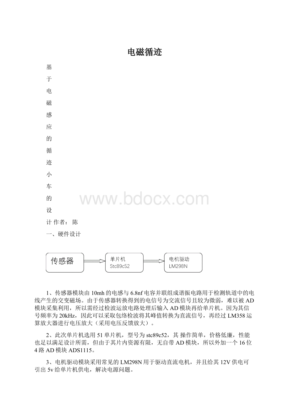
一、硬件设计
1、传感器模块由10mh的电感与6.8nf电容并联组成谐振电路用于检测轨道中的电线产生的交变磁场。
由于传感器转换得到的电信号为交流信号且较为微弱,难以被AD模块采集利用,所以需经过检波运放电路处理后输入AD模块再给单片机。
因为其信号频率为20kHz,因此可以采取包络检波将其峰值转换为直流信号,再经过LM358运算放大器进行电压放大(采用电压反馈放大)。
2、此次单片机选用51单片机,型号为stc89c52,其操作简单,价格低廉,性能也足以满足设计所需,但由于其片内资源有限,无自带AD模块,所以外加一个16位4路AD模块ADS1115。
3、电机驱动模块采用常见的LM298N用于驱动直流电机,并且给其12V供电可引出5v给单片机供电,解决电源问题。
检波放大电路图如下:
单片机与AD模块连接图如下:
二、软件设计
是
即A1-A2<设定值
设定值需根据实际
调试测得否
是
否是
..\参考资料\ADS1115中文资料.pdf
主要通过IIC时序读取返回值,需要配置三个寄存器,
详见参考资料。
三、调试
数码管显示返回数值,在跑道上纪录直道,左右转各自的数值范围,用于程序调试最终适应相关跑道。
(因完成的比较仓促,并未运用PID算法,在低速下足以循迹)
四、附录
电路仿真图:
实物图:
参考程序:
#include
#include
#defineucharunsignedchar
#defineuintunsignedint
sbitpwm_r=P2^0;
sbitpwm_l=P2^1;
sbitSDA=P1^0;
sbitSCL=P1^1;
sbitDU=P2^6;//数码管段选
sbitWE=P2^7;//数码管位选
uintwidthL=39;
uintwidthR=37;
uintfre=40;
inta;
ucharcodetable[]={
//012345678
0x3F,0x06,0x5B,0x4F,0x66,0x6D,0x7D,0x07,0x7F,
//9ABCDEF-.关显示
0x6F,0x77,0x7C,0x39,0x5E,0x79,0x71,0x40,0x80,0x00
};
/*====================================
数码管位选码
====================================*/
//第1位2位3位4位5位6位7位8位
ucharcodeT_COM[]={0xfe,0xfd,0xfb,0xf7,0xef,0xdf,0xbf,0x7f};//数码管位码
/*5us延时*/
voiddelay_5us()
{
_nop_();
}
/*1Ms延时*/
voiddelay(uintz)
{
uintx,y;
for(x=z;x>0;x--)
for(y=114;y>0;y--);
}
voidDisplay(uintValue)
{
//------------------------------
DU=1;
P0=table[Value/10000];
DU=0;
P0=0xff;
WE=1;
P0=T_COM[0];
WE=0;
delay(3);
//-------------------------------
DU=1;
P0=table[Value%10000/1000];
DU=0;
P0=0xff;
WE=1;
P0=T_COM[1];
WE=0;
delay(3);
//-------------------------------
DU=1;
P0=table[Value%10000%1000/100];
DU=0;
P0=0xff;
WE=1;
P0=T_COM[2];
WE=0;
delay(3);
//-------------------------------
DU=1;
P0=table[Value%10000%1000%100/10];
DU=0;
P0=0xff;
WE=1;
P0=T_COM[3];
WE=0;
delay(3);
//-------------------------------
DU=1;
P0=table[Value%10000%1000%100%10];
DU=0;
P0=0xff;
WE=1;
P0=T_COM[4];
WE=0;
delay(3);
}
/*1Ms延时*/
/*voiddelay(uintz)
{
uintx,y;
for(x=z;x>0;x--)
for(y=114;y>0;y--);
}*/
/*****************I2C部分********************/
/*I2C初始化*/
voidI2C_init()
{
SDA=1;
_nop_();
SCL=1;
_nop_();
}
/*I2C起始信号*/
voidI2C_Start()
{
SCL=1;
_nop_();
SDA=1;
delay_5us();
SDA=0;
delay_5us();
}
/*I2C终止信号*/
voidI2C_Stop()
{
SDA=0;
_nop_();
SCL=1;
delay_5us();
SDA=1;
delay_5us();
}
voidrespons()
{
SCL=1;
_nop_();
SDA=0;
_nop_();
SCL=0;
_nop_();
}
voidnorespons()
{
SCL=1;
_nop_();
SDA=1;
_nop_();
}
/*发送一个字节*/
voidI2C_send_byte(ucharbyte)
{
uchari;
for(i=0;i<8;i++)
{
SCL=0;
_nop_();
if(byte&0x80)
{
SDA=1;
_nop_();
}
else
{
SDA=0;
_nop_();
}
SCL=1;
_nop_();
byte<<=1;//01010100B
}
SCL=0;
_nop_();
SDA=1;
_nop_();
}
/*I2C读一字节*/
ucharI2C_read_byte()
{
uchardat,i;
SDA=1;
_nop_();
SCL=0;
_nop_();
for(i=0;i<8;i++)
{
SCL=1;
_nop_();
if(SDA)
dat|=0x01;
if(i<7)
dat<<=1;
SCL=0;
_nop_();
}
returndat;
}
/*****************AD模块部分********************/
/*ADS1115写入数据*/
voidconfige_write()
{
I2C_Start();
I2C_send_byte(0x90);
respons();
I2C_send_byte(0x01);
respons();
I2C_send_byte(0x82);
respons();
I2C_send_byte(0xe3);
respons();
I2C_Stop();
}
voidpointer()
{
I2C_Start();
I2C_send_byte(0x90);
respons();
I2C_send_byte(0x00);
respons();
I2C_Stop();
}
/*ADS1115读取数据*/
uintconversion_read()
{
ucharresulth,resultl;
uintresult;
I2C_Start();
I2C_send_byte(0x91);
respons();
resulth=I2C_read_byte();
norespons();
resultl=I2C_read_byte();
norespons();
result=resulth<<8|resultl;
returnresult;
}
uintget_ad()
{
uintvalue;
confige_write();
delay_5us();
pointer();
delay_5us();
value=conversion_read();
returnvalue;
}
/*****************初始化********************/
voidinit()//2ms/40=0.05ms
{
TMOD=0x02;
TH0=210;
TL0=210;
ET0=1;//开定时器0中断
TR0=1;//启动定时器0
EA=1;//开总中断
}
/*****************主函数********************/
voidmain()
{
init();
I2C_init();
while
(1)
{
a=get_ad();
if(~a>3000&&~a<30000)
{
widthL=0;
widthR=18;
}
elseif(a>3000&&a<30000)
{
widthL=19;
widthR=0;
}
else{
widthL=25;
widthR=24;
}
}
}
/*****************定时器0中断,产生pwm********************/
voidt0_int()interrupt1
{
staticintcount;
count++;
if(count>widthL)
pwm_l=0;
if(count>widthR)
pwm_r=0;
if(count==fre)
{
count=0;
pwm_r=pwm_l=1;
}
}
 升级会员
升级会员 