跑步机总体结构设计.docx
《跑步机总体结构设计.docx》由会员分享,可在线阅读,更多相关《跑步机总体结构设计.docx(28页珍藏版)》请在冰豆网上搜索。
跑步机总体结构设计
(57)ABSTRACT
Anexercisetreadmillisdisclosedwhichincludesvariousfeaturestoenhanceuseroperationandtoreducemaintenancecosts.Thesefeaturesincludehandlebarswithanupwardlycurvedcentersectionandoutwardlyflaredsideportionsalongwithpivotingrearlegsforthetreadmillframe.Thecontrolpanelfeaturesincludesnap-inusertraysandanoverlaycoveringthenumericalkeypadalongwithanauxiliarycontrolpanelhavingasubsetofusercontrolsthatarelargerandmoreeasytousethanthesamecontrolsonthemaincontrolpanel.Maintenanceenhancingfeaturesincludetheprovisionforaccesspanelsinthetreadmillhousingandabeltlubricationsystemthatusesaprimingpulsetoclearthewaxsprayingnozzlealongwithusingtreadmilloperatingcriteriaforschedulingandoperatingthelubricationsystem.Forinjectionmoldedpartssuchasthecontrolpanel,structuralstrengthisenhancedbyutilizinggas-assistinjectionmoldingtoformstructuralribs.Anotherfeatureincludespre-glazingthetreadmillbelt.Soundandvibrationarereducedinatreadmillbymountingthetreadmillbeltdrivemotoronmotorisolationmountsthatincluderesilientmembers.Afurtherfeatureisadoublesidedwaxeddeckwhereonesideofthedeckiscoveredbyaprotectivetape.
11Claims,24DrawingSheets
1
TREADMILLMECHANISM
CROSS-REFERENCETORELATED
APPLICATIONS
5
ThisapplicationisadivisionalofapplicationSer.No.10/437,111,filedMay13,2003,nowU.S.Pat.No.6,899,659whichinturniscontinuationofapplicationSer.No.09/944,141,filedSep.4,2001,nowU.S.Pat.No.6,572,512,whichinturnisacontinuationinpartofapplicationSer.No.09/651,247,filedAug.30,2000,nowU.S.Pat.No.6,776,740andpriorityclaimedunderprovisionalapplicationsSer.No.60/159,268filedOct.13,1999and60/152,657filedSep.7,1999.
15
FIELDOFTHEINVENTION
Thisinventiongenerallyrelatestoexerciseequipmentandinparticulartoexercisetreadmills
20
BACKGROUNDOFTHEINVENTION
Exercisetreadmillsarewidelyusedforperformingwalkingorrunningaerobic-typeexercisewhiletheuserremainsinarelativelystationaryposition.Inadditionexercisetread-millsareusedfordiagnosticandtherapeuticpurposes.Generally,forallofthesepurposes,thepersononthetreadmillperformsanexerciseroutineatarelativelysteadyandcontinuouslevelofphysicalactivity.OneexampleofsuchatreadmillisprovidedinU.S.Pat.No.5,752,897.30
Althoughexercisetreadmillshavereachedarelativelyhighstateofdevelopment,thereareanumberofsignificantimprovementsinthemechanicalstructureofatreadmillthatcanimprovetheuser'sexerciseexperienceaswellimprovethemaintainabilityandreducethecostofmanufactureof35treadmills.
SUMMARYOFTHEINVENTION
Itisthereforeanobjectoftheinventiontoprovidean40exercisetreadmillhavinganimprovedmechanicalarrangement.
Itisalsoanobjectoftheinventiontoprovideanexercisetreadmillwithanupwardlycurvingcenterhandlebarthatallowstheusertograspthehandlebaratanumberof45differentheightsandprovidesadditionalkneeroomforauserrunningonthetreadmill.
Anadditionalobjectoftheinventionistoprovideanexercisetreadmillwithapairofsidehandrailswheretherearportionsflairoutwardly.
Anotherobjectoftheinventionistoprovideanexercisetreadmillwithpivotingrearlegs.
Stillanotherobjectoftheinventionistoprovideanexercisetreadmillhavingasnap-inaccessorytray.55
Anadditionalobjectoftheinventionistoprovidearemovableoverlayovercertainportionsofatreadmillcontrolpanelsuchasakeypad.
Itisstillanotherobjectoftheinventiontoprovideatreadmillhavingacontrolpanelthatincludesusercontrols60withanauxiliarycontrolpanelhavingasubsetoftheusercontrols.
Itisalsoanobjectoftheinventiontoprovideahousingcoveringatreadmillframewithanaccesspaneltoprovidereadyaccesstovariouscomponentsofthetreadmillincludinginsometreadmillscomponentsofabeltlubricationsystem.
2
Additionally,itisanobjectoftheinventiontoprovideatreadmillbeltlubricationsystem,wherealubricantsuchaswaxissprayedonthebeltfromanozzle,withamechanismforsprayingaprimingpulseofthelubricantthroughthenozzleofthesystempriortothenormalbeltsprayingoperationofthesystem.Operationofthelubricationsystemcanbeenhancebyutilizingtreadmilloperatingcriteriatobothschedulebeltlubricationsandtosequencetheactuallubricationprocessincludingtheprimingpulse.
Afurtherobjectoftheinventionistoprovideanexercisetreadmillhavingacontrolpanelhavingsupportribsformedfromgas-assistmoldedinjectedplastic.
Stillanotherobjectoftheinventionistoprovideatreadmillwithabelthavingapre-glazedsurface.
Yetanotherobjectoftheinventionistoprovideanexercisetreadmillhavingamotorconnectedtoapulleyformovingabeltwherethemotorissecuredtotheframeofthetreadmillbyamountingstructurethatincludesresilientmemberstoisolatetheframefrommotorvibration.
Afurtherobjectoftheinventionistoprovideanexercisetreadmillwithadoublesideddeckhavingitsundersidecoveredbyaprotectivetapetoprotectthewaxedsurface.
BRIEFDESCRIPTIONOFTHEDRAWINGS
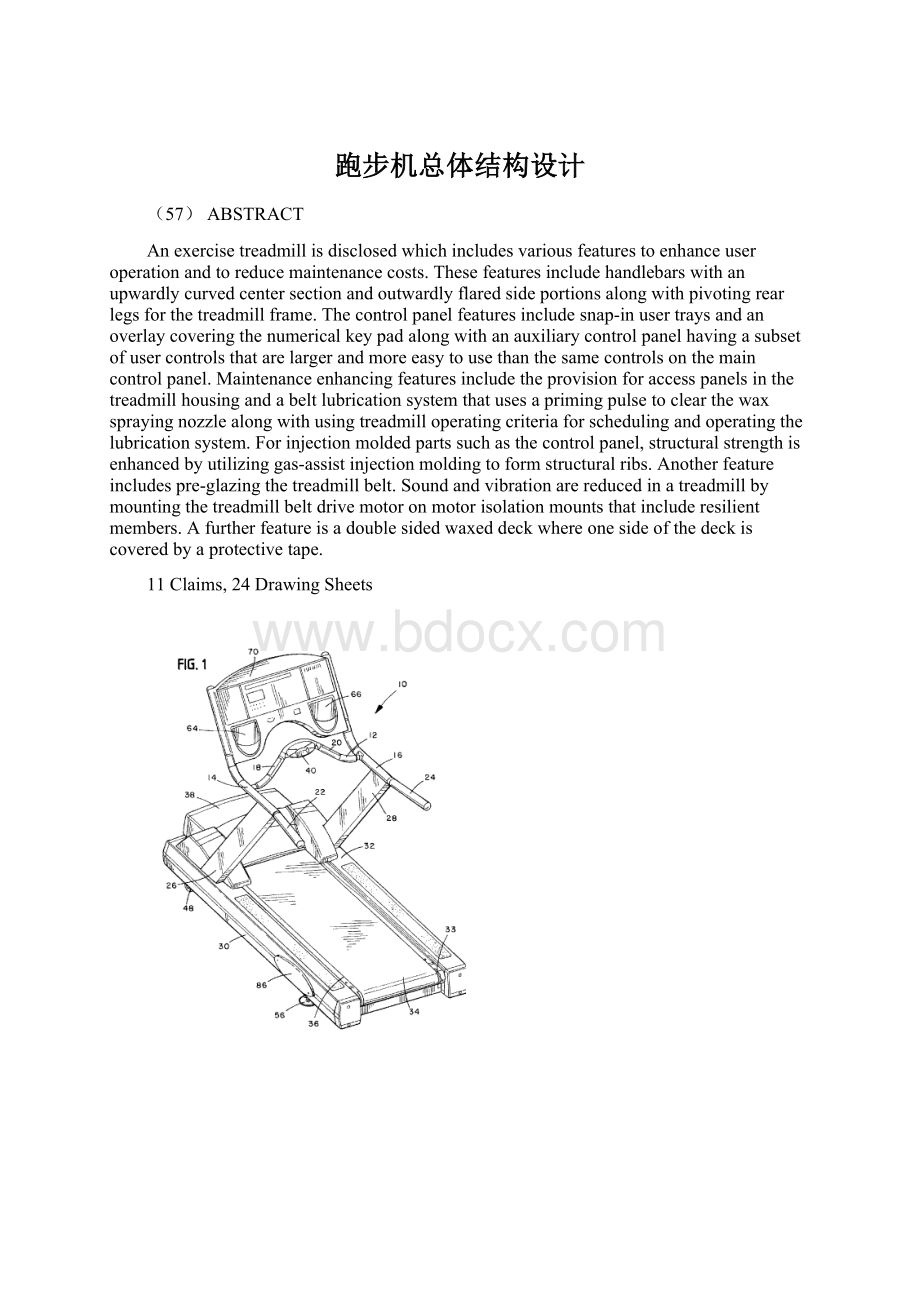
FIG.1.isaperspectiveviewofanassembledexercisetreadmillaccordingtotheinvention;
FIG.2isatopplanviewoftheassembledexercisetreadmillofFIG.1illustratingtheoutwardflareofapairofsidearmhandles;
FIGS.3-7areviewsofacentralarmhandleofthetreadmillofFIG.1;
FIGS.8A-BaresideviewsofthetreadmillofFIG.1illustratingapivotingrearfootassembly;
FIG.9AisaperspectiveviewofapadassemblyforusewiththepivotingfootassemblyofFIG.8;
FIG.9BisasectionedsideviewofthepadassemblyforusewiththepivotingfootassemblyofFIG.9A;
FIG.10isapartial,explodedperspectiveviewofthecontrolpanelusedintheexercisetreadmillofFIG.1illustratingapairofsnap-inaccessorytraysandaremovableoverlay;
FIG.11Aisaperspectiveviewofanassembledexercisetreadmillshowingthelocationofanauxiliarycontrolpanelaccordingtotheinvention;
FIG.11BisanenlargedperspectiveviewofthelocationofanauxiliarycontrolpanelofFIG.11A;
FIG.12AisaperspectiveviewofanassembledauxiliarycontrolpanelofFIGS.11A-B;
FIG.12BisanexplodedperspectivetopviewoftheassembledauxiliarycontrolpanelofFIGS.11A-B;
FIG.12CisanexplodedperspectivebottomviewoftheassembledauxiliarycontrolpanelofFIGS.11A14B;
FIG.13isapartial,explodedperspectiveviewoftheexercisetreadmillofFIG.1illustratingaremovableaccesspanel;
FIG.14isapartial,brokenaway,topplanviewofthetreadmillofFIGS.1and2showingabeltlubricationmechanism;
FIG.15isasectioneddrawingofaportionoftheexercisetreadmillofFIG.1illustratingtheformationofastructuralribformedbygas-assistinjectionmolding;
FIG.16isatopplanviewofalowerhousingofthecontrolpanelofFIG.10illustratingstructuralcomponentsformedbythegas-assistinjectionmoldingmethodofFIG.15;
3
FIG.17isanillustrationofawovenbelthavingaglazedsurfaceforusewiththetreadmillsofFIGS.1and11;
FIG.18isasectioned,partialsideviewofatreadmillofthetypeinFIG.11havingafirstembodimentofamotorisolationmountaccordingtotheinvention;
FIG.19isanexplodedperspectiveviewofthemotorisolationmountofFIG.18;
FIG.20isanassembledperspectiveviewofthemotorisolationmountofFIG.18;
FIG.21isanexplodedperspectiveviewofasecondembodimentofamotorisolationmount;
FIG.22isanassembledperspectiveviewofthesecondembodimentofamotorisolationmountofFIG.21;
FIG.23isatopviewofathirdembodimentofamotorisolationmount;
FIG.24isabottomperspectiveviewofthethirdembodimentofamotorisolationmountofFIG.23;
FIG.25isasideviewofthethirdembodimentofthemotorisolationmountofFIG.23;
FIG.26isaplanviewofanundersideofadoublesided20treadmilldeckaccordingtotheinvention;
FIG.27isablockdiagramofthecontrolsystemsuitableforusewiththetreadmillsofFIGS.1-28;and
FIGS.28A-CdepictaflowchartillustratingtheoperationofthebeltlubricatingsystemofFIG.14.
DETAILEDDESCRIPTIONOFTHE
INVENTION
FIG.1showsthegeneralouterconfigurationofanexercisetreadmill10,accordingtotheinvention,wherethetreadmillincludesacentralarmhandle12thatextendsupwardlyfromapairofsidehandrails14and16.Inthepreferredembodimentoftheinvention,thecentralarmhandle12iscurvedinthegeneralshapeofanarc.Byprovidinganupwardextensioninthecenterarmhandle12,itmakesitpossiblefortreadmilluserstograspthecentralhandle12inanumberofdifferentverticallocationsandalsoaccommodatesthekneesofuserswhomightberunningclosetothefrontofthetreadmill10.Includedinthecentralarmhandle12inoneembodimentoftheinventionareapairofelectrodes18and20forobtainingtheuser'sheartrateasgenerallytaughtinLeonetal,U.S.Pat.No.5,365,934.Amoredetailedviewofthearmhandle12isprovidedinFIGS.23-27.Oneadvantageofplacingtheelectrodes18and20ontheupwardextendingportionsofthecentralarmhandle12asshowninFIG.1isthatitmakesitsignificantlymoreconvenientforsomeuserstograsptheelectrodes18and20whilerunningonthetreadmill10.
FIGS.1and2illustrateanotherfeatureoftheinventionwhereeachofthesidehandrails14and16havearearportion22and24
 升级会员
升级会员 