Finite Element Analysis Report for Drying Raw Mill new.docx
《Finite Element Analysis Report for Drying Raw Mill new.docx》由会员分享,可在线阅读,更多相关《Finite Element Analysis Report for Drying Raw Mill new.docx(13页珍藏版)》请在冰豆网上搜索。
FiniteElementAnalysisReportforDryingRawMillnew
FiniteElementAnalysisReportforDryingRawMill
1.Introduction
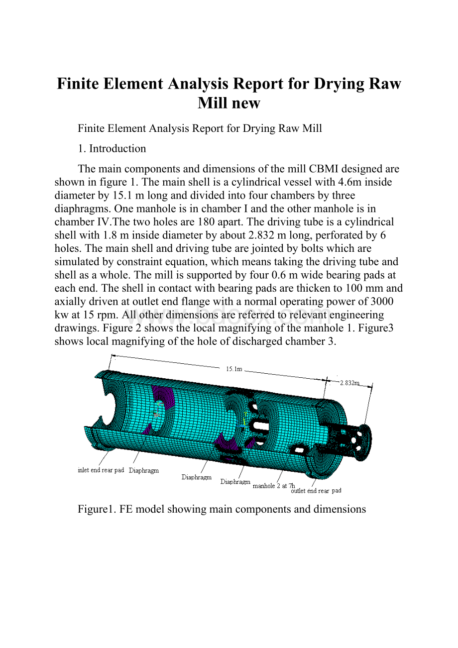
ThemaincomponentsanddimensionsofthemillCBMIdesignedareshowninfigure1.Themainshellisacylindricalvesselwith4.6minsidediameterby15.1mlonganddividedintofourchambersbythreediaphragms.OnemanholeisinchamberIandtheothermanholeisinchamberⅣ.Thetwoholesare180apart.Thedrivingtubeisacylindricalshellwith1.8minsidediameterbyabout2.832mlong,perforatedby6holes.Themainshellanddrivingtubearejointedbyboltswhicharesimulatedbyconstraintequation,whichmeanstakingthedrivingtubeandshellasawhole.Themillissupportedbyfour0.6mwidebearingpadsateachend.Theshellincontactwithbearingpadsarethickento100mmandaxiallydrivenatoutletendflangewithanormaloperatingpowerof3000kwat15rpm.Allotherdimensionsarereferredtorelevantengineeringdrawings.Figure2showsthelocalmagnifyingofthemanhole1.Figure3showslocalmagnifyingoftheholeofdischargedchamber3.
Figure1.FEmodelshowingmaincomponentsanddimensions
Figure2.localmagnifyingofthemanhole1
Figure3.localmagnifyingoftheholeofdischargedchamber3
2.Boundaryconditions
3-Dstructureelementandquadraticshellelementareusedtomodelthemill.
2.1Drivingtorqueandoffsetload
AdrivingtorqueT=1910000N.mwhichcorrespondstoabout3000kwat15rpmisappliedbycircumferentialforcesonendflange.Aloadof200736.3kginternalballsandmaterialisappliedasadditionalmassonbottompartofmainshellandoffsettotheleftasillustratedinfigure4.TheangularpositionsofAandBareapproximately-1800and-600respectively,foundbytrialanderrorsoastocounterbalancetheappliedadditionalmass.
Figure4.Drivingtorqueandoffsetload
Figure5Modelof8supportpads
2.2Linermasses
7559kgforheadlineratinletend,7942kgforheadlineratoutletend,14782.56kgforshelllinerinchamberI,38088kgforshelllinerinchamberⅡ,10760kgforshelllinerinchamberⅢ,22954kgforshelllinerinchamberⅣareappliedasadditionaldistributedmassofcorrespondingcomponents(headplatesandmainshell).
2.3Diaphragm
16402kgweightfordiaphragmbetweenchamberIandⅡ,8201kgweightforthetwodiaphragmsrespectivelyindischargedchamberⅢ,alltheweightsareappliedasdistributedmassofanannularplateusingverysmallYoung'smodulussothatthediaphragmdoesnotcontributetothestiffnessoftheshell.
2.4Drivingtubeandshellmasses
12399kgfordrivingtube(SeedrawingNO.BMRaCD46.3.7),122683kgforshell(SeedrawingNO.BMRaCD4685/35.3.4),alloftheweightswillbecalculatedbydefiningdenseofthematerialthroughANSYSsystem,andultimatelyappliedtothemodel.
2.5Support
Thecontactmodelisintroducedtosimulatethefrictionlesscontactbetweenshellringsandthe200mmthicksupportpads.Radialreactionsillustrateinfigure5.
Totally,12modelsarestudied,eachoneforeveryhourpositioninaccordingtothepositionofpads,andonlyimportantandcriticalresultsarereportedbelow.
3.Resultanalysis
3.1Resultsforforcesandstressesonpads
Asillustratedinfigure5andthroughcontactmodelsimulation,
=551380,
=592676,
=666763N,
=964697N,
=581772N,
=557564N,
=581077N,
=948661N,finallytheverticalreactiontotallyequalsto4697300N(about479.36tons).
With0.2mthickplatesforpads,themaximumVonMisesstressis7.57MPa(figure6).Foranyotherthicknessofpads,byfunction
=
inMPaandtinmeter,basedonthefactthatbendingstressinplatesisinverselyproportionaltothesquareofitsthickness(
=
).Usingtheyieldstrength185MPaofthepadsmaterialandsafetyfactor2,thefunctiongivesthethicknessofpadsis57mm.
Figure6ThemaximumVonMisesstressinpads
Padshaveasafetyfactorgreaterthan2whiletheyarestrongerthan57mmthickplate.
3.2Maximumstressindrivingtube
Asillustratedinfigure7,"TheVonMisesstressdistributionofdrivingtube"showsthemaximumVonMisesstressis17.6MPa.Consideringthestartuptorque2.5timesgreater,thenthesafetyfactoragainstyieldis200/17.6/2.5=4.54.Figure8showsthemaximumVonMisesstressofdrivingtubehole,whichis4.17MPa,muchsmallerthanthematerialbreakagelimit.
Figure7TheVonMisesstressdistributionofdrivingtube
Figure8TheVonMisesstressdistributionofdrivingtubehole
3.3stressanalysisofmanholes
3.3.1VonMisesstressaroundmanhole
Formanhole1,themaximumstaticVonMisesstressis66.7MPaat4hposition(seeFig9);formanhole2,themaximumstaticVonMisesstressis79.4MPaat4hposition(seeFig10);thesafetyfactorwithrespecttoyieldisf=250/79.4=3.15
Fig9MaximumVonMisesStressaroundmanhole1
Fig10MaximumVonMisesStressaroundmanhole2
3.3.2Fatiguestressaroundmanhole
Formanhole1,theworstprincipalstressrangeoccursontheedgeofshellbetween
maxat4h=68.4Mpaand
minat7h=-12.9Mpa(Fig11-12).Thus,stressrange=68.4-(12.9)=81.3Mpa.SafetyfactorwithrespecttoallowableinfinitelifecategoryAstressaccordingtoAISC:
f=165(Mpa)/(81.3Mpa)=2.02。
Fig11Max.principalstressonmanhole1
Fig12Min.principalstressonmanhole1
Formanhole2,theworstprincipalstressrangeoccursontheedgeofshellbetween
maxat10h=82.1Mpaand
minat2h=-19.7Mpa(Fig13-14).Thus,stressrange=82.1-(19.7)=101.8Mpa.SafetyfactorwithrespecttoallowableinfinitelifecategoryAstressaccordingtoAISC:
f=165(Mpa)/(101.8Mpa)=1.62。
Fig13Max.principalstressonmanhole2
Fig14Min.principalstressonmanhole2
3.4Fatiguestressarounddischargedhole
Forthesymmetricalcharacteristicsoftheholeinthedischargedpart,thisreportjuststudiesoneholewiththesamepositionofmanhole1ofeveryhourposition.
Forthedischargedhole,theworstprincipalstressrangeoccursontheedgeofinsideshellbetween
maxat4h=45.5Mpaand
minat10h=-14.7Mpa(Fig15-16).Thus,stressrange
=45.5-(-14.7)=60.2Mpa.SafetyfactorwithrespecttoallowableinfinitelifecategoryAstressaccordingtoAISC:
=(165Mpa)/(60.2Mpa)=2.74
Fig15Max.principalstressondischargedhole
Fig16Min.principalstressondischargedhole
3.5Fatiguestressof“T”shapebuttjoint
Forthesymmetricalcharacteristicsofsliderring,takeonesideofthe“T”shapebuttjointinthepositionofinletendforexample.Theworstprincipalstressrangeoccursontheedgeofshellbetween
maxat1h=2.35Mpaand
minat3h=-9.5Mpa(Fig17-18).Thus,stressrange
=2.35-(-9.5)=11.85Mpa.SafetyfactorwithrespecttoallowableinfinitelifecategoryAstressaccordingtoAISC:
=(165Mpa)/(11.85Mpa)=13.92
Fig17Max.principalstressof“T”shapebuttjoint
Fig18Min.principalstressof“T”shapebuttjoint
4Generalconlusions
1.Thesafetyfactorwithrespecttoyieldofmanholesandmainshell=3.15whichmeetthestrengthrequirement.
2.Formanhole1,fatiguestressrange=81.3Mpa,safetyfactor=2.02;formanhole2,fatiguestressrange=101.8Mpa,safetyfactor=1.62;fordischargedhole,fatiguestressrange=60.2Mpa,safetyfactor=2.74.For“T”shapebuttjoint,fatiguestressrange=11.85Mpa,safetyfactor=13.92.Thefatiguestrengthofmanholesmeetdesignrequirement.
3.Themaximumstressondrivingtube=17.6Mpa,consideringthestartuptorque2.5timesgreater,safetyfactor=4.54,whicharesafeenough.
4.ThemaximumVonMisesstressofbearingpads=7.57Mpa.ThemaximumVonMisesstressofthecontactsurfaceofsliderring=10.0Mpa.
Inaword,thedesignofmillmeetsstaticandfatiguerequirement.
 升级会员
升级会员 