计算机网络基础模拟器实验报告Word文档下载推荐.docx
《计算机网络基础模拟器实验报告Word文档下载推荐.docx》由会员分享,可在线阅读,更多相关《计算机网络基础模拟器实验报告Word文档下载推荐.docx(9页珍藏版)》请在冰豆网上搜索。
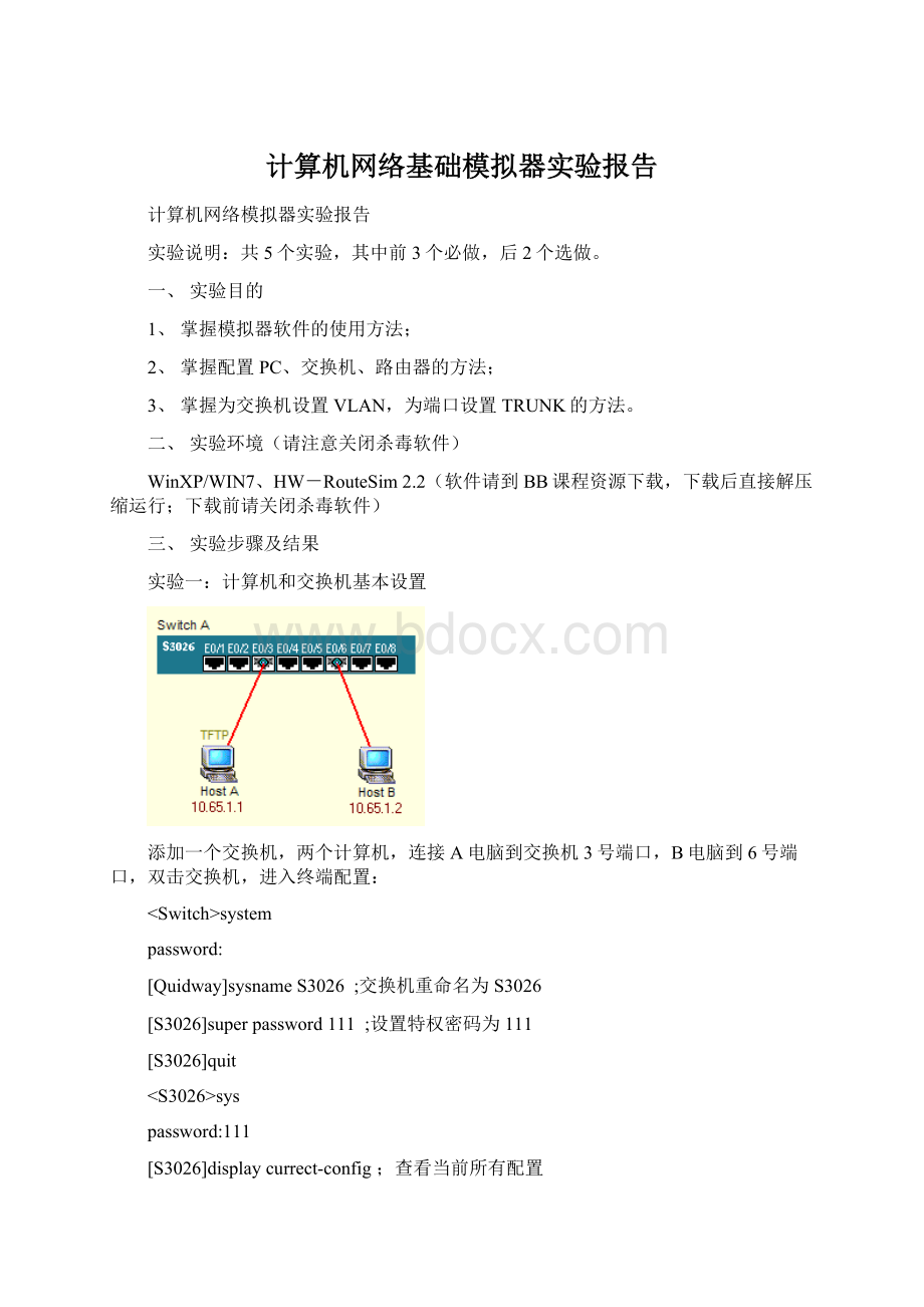
设置特权密码为111
[S3026]quit
S3026>
sys
111
[S3026]displaycurrect-config;
查看当前所有配置
[S3026]displayvlanall;
查看当前VLAN设置
观察此时所有交换机端口都在同一个vlan1内。
双击小电脑A:
login:
root
linux
[root@PCAroot]#?
;
输入?
号查看命令提示
[root@PCAroot]#ifconfigeth010.65.1.1netmask255.255.0.0
双击小电脑B:
[root@PCAroot]#ifconfigeth010.65.1.2netmask255.255.0.0
点击A电脑做测试:
[root@PCAroot]#ping10.65.1.2
实验结果及其分析:
(将结果保存为文件net1.txt)
[root@PCAroot]#ping10.65.1.2
64bytesfrom10.65.1.1:
icmp_seq=1ttl=128time=0.207ms
icmp_seq=1ttl=128time=0.100ms
icmp_seq=1ttl=128time=0.96ms
4packetstransmitted,4received,0%loss,time2000ms
试验二:
基本VLAN设置
添加2台交换机,4台计算机。
连接A电脑到A交换机3号端口,B电脑到6号端口;
连接C电脑到B交换机3号端口,D电脑到6号端口;
将A交换机的8号端口与B交换机的1号端口连接。
分别设置计算机的IP为:
PCA:
10.65.1.1PCB:
10.66.1.1PCC:
10.65.1.3PCD:
10.66.1.3掩码都是255.255.0.0
此时,PCA与PCC在同一个子网10.65.0.0内;
PCB与PCD在同一个子网10.66.0.0内;
默认交换机设置下,PCA能与PCC连通,PCB能与PCD连通。
继续本实验:
......;
登录交换机过程省略
[SwitchA]vlan2;
创建vlan2
[SwitchA-vlan2]porte0/3toe0/4
[SwitchA]vlan3
[SwitchA-vlan3]porte0/5toe0/6
[SwitchB]vlan2
[SwitchB-vlan2]porte0/3toe0/4
[SwitchB]vlan3
[SwitchB-vlan3]porte0/5toe0/6
分别查看各交换机的VLAN设置,然后测试连通性:
[root@PCAroot]#ping10.65.1.1通(本机IP)
[root@PCAroot]#ping10.65.1.3不通(中间连接线是vlan1)
[root@PCAroot]#ping10.66.1.1不通(不同网络,不同vlan)
[root@PCAroot]#ping10.66.1.3不通(不同网络,不同vlan)
[root@PCBroot]#ping10.66.1.3不通(中间连接线是vlan1)
将PCA改接到SwitchAE0/2(vlan1)
[root@PCAroot]#ping10.65.1.3不通(同网络,不同vlan)
将PCC改接到SwitchBE0/2(vlan1)
[root@PCAroot]#ping10.65.1.3通(同网络,同在vlan1)
再改回来:
将PCA接回到SwitchAE0/3(vlan1)
将PCC接回到SwitchBE0/3(vlan1)
并设置trunk:
[S3026A]interfaceethernet0/8
[S3026A-Ethernet0/8]portlink-typetrunk
[S3026A-Ethernet0/8]porttrunkpermitvlanall
[S3026B]interfaceethernet0/1
[S3026B-Ethernet0/1]portlink-typetrunk
[S3026B-Ethernet0/1]porttrunkpermitvlanall
[root@PCAroot]#ping10.65.1.3通
[root@PCAroot]#ping10.66.1.3不通
[root@PCBroot]#ping10.66.1.3通
即:
PCA和PCC同在vlan2是通的,PCB和PCD同在vlan3是通的。
PCA和PCB是不通的。
同理PCC和PCD也是不通的。
注意:
交换机默认没有设置trunk,所有接口默认vlan1,对于交换机而言,trunk要成对出现。
(将结果保存为文件net2.txt)
试验三:
直连路由
Quidwqy>
[Quidway]interfaceethernet0
[Quidway-Ethernet0]ipaddr10.65.1.2255.255.255.0
[Quidway-Ethernet0]undoshutdown
[Quidway-Ethernet0]inte1
[Quidway-Ethernet1]ipaddr10.66.1.2255.255.255.0
[Quidway-Ethernet1]undoshutdown
[root@PCAroot]#ifconfigeth010.65.1.1netmask255.255.255.0
[root@PCBroot]#ifconfigeth010.66.1.1netmask255.255.255.0
[root@PCAroot]#ping10.65.1.2(通,没有网关只能ping直连的口)
[root@PCAroot]#ping10.66.1.2(不通,PCA没有设置网关)
[root@PCAroot]#routeadddefaultgw10.65.1.2
[root@PCAroot]#ping10.66.1.2(通)
[root@PCAroot]#ping10.66.1.1(不通,因PCB没有网关)
[root@PCBroot]#routeadddefaultgw10.66.1.2
[root@PCAroot]#ping10.66.1.1(通)
去掉计算机HostB与Router的连线,再ping:
[root@PCAroot]#ping10.66.1.2不通(没有接线端口会自动down掉)
再连接HostB与Router的连线,再ping:
(将结果保存为文件net3.txt)
试验四:
单臂路由
设置PCAip:
10.65.1.1255.255.255.0gateway:
10.65.1.2
设置PCBip:
10.66.1.1255.255.255.0gateway:
10.66.1.2
单臂路由可以有2种情况实现:
1.一个vlan下的单臂路由(一个接口两个IP的情况)
在一个vlan下,可以通过设置路由器端口的secondaryip实现在一个物理网络上两个具有不同网段IP计算机的联通。
[Quidway]interfaceethernet0;
进入端口0
[Quidway-Ethernet0]ipaddr10.65.1.2255.255.255.0;
设置主ip
[Quidway-Ethernet0]ipaddr10.66.1.2255.255.255.0secondary
;
设置副ip
[Quidway-Ethernet0]undoshutdown;
重启端口
[Quidway-Ethernet0]quit;
退出端口设置
[Quidway]iprouting;
启动路由
[Quidway]discur;
查看设置正确与否
此时测试:
[root@PCAroot]#ping10.66.1.1通
由此可以看出,PCA与PCB之间的发送的数据包是经过路由器的,从路由器E0入,再从E0出,所以称之为单臂路由。
这种情况PCA和PCB在链路层是同一个广播域,对网络带宽不利。
如果划分VLAN可以隔离广播域。
通过子接口可以实现对不同VLAN的路由。
2.子接口单臂路由
路由器一个接口划分两个子接口,对两个vlan实现路由。
(该步骤试验方法,我在思科的模拟器上测试成功,但在华为的该版本模拟器中无法实现子接口的配置,有兴趣的同学请钻研一下。
只需知道有这种方法即可,其它不做要求)
本实验接上一个实验,计算机和交换机的IP地址和网关不变,但要求交换机工作在两个VLAN的情况下。
当交换机设置成两个vlan时,逻辑上已经成为两个网络,广播被隔离了。
两个vlan的网络要通信,必须通过路由器,如果接入路由器的一个物理端口,则必须有两个子接口分别与两个vlan对应,同时还要求与路由器相联的交换机的端口E0/1要设置为trunk,因为这个口要通过两个vlan的数据包。
对于前述secondaryip的情况,实质上是一个接口,不能实现对两个vlan的路由。
首先需要初始化路由器A,然后分别设置。
[SwitchA]vlan2
[SwitchA-vlan2]porte0/2
[SwitchA-vlan3]porte0/7
[SwitchA]inte0/1
[SwitchA-Ethernet0/1]portlink-typetrunk
[SwitchA-Ethernet0/1]porttrunkpermitvlanall
[SwitchA-Ethernet0/1]porttrunkencapdot1q
[SwitchA]discurr
[Quidway]inte0
[SwitchA-Ethernet0]inte0.1;
设置子接口
[SwitchA-Ethernet0.1]encapsulationdot1q1
[SwitchA-Ethernet0.1]ipaddr10.65.1.2255.255.255.0
[SwitchA-Ethernet0.1]undoshut
[SwitchA-Ethernet0.1]inte0.2
[SwitchA-Ethernet0.2]encapsulationdot1q2
[SwitchA-Ethernet0.2]ipaddr10.66.1.2255.255.255.0
[SwitchA-Ethernet0.2]undoshut
(将结果保存为文件net4B.txt)
试验五:
地址转换配置NAT(仅供有兴趣的同学探讨,不做要求)
设置公司三个公网IP:
133.0.0.1、133.0.0.2、133.0.0.3。
为地址池pool。
内部网络10.1.0.0网络可以通过公网IP访问外部计算机。
自动转换成公网IP。
设置:
HostA:
10.1.1.1255.255.0.0
HostB:
10.1.1.2255.255.0.0
HostC:
10.1.1.3255.255.0.0
HostD:
10.2.1.1255.255.0.0
RouterAE0:
10.1.1.9255.255.0.0
HostE:
133.0.0.8255.255.0.0
[Quidway]nataddress-group133.0.0.1133.0.0.3pool1
[Quidway]acl1
[Quidway-acl-1]rulepermitsource10.1.0.00.0.255.255
[Quidway-acl-1]ruledenysourceany
[Quidway-acl-1]ints0
[Quidway-Serial0]undoshut
[Quidway-Serial0]natoutbound1address-grouppool1
[Quidway-Serial0]natserverglobal133.0.0.1inside10.1.1.1ftptcp
[Quidway-Serial0]natserverglobal133.0.0.2inside10.1.1.2wwwtcp
[Quidway-Serial0]natserverglobal133.0.0.3inside10.1.1.3smtpudp
(将结果保存为文件net5.txt)
 升级会员
升级会员 