PST 645U变压器保护测控装置技术说明书Word下载.docx
《PST 645U变压器保护测控装置技术说明书Word下载.docx》由会员分享,可在线阅读,更多相关《PST 645U变压器保护测控装置技术说明书Word下载.docx(37页珍藏版)》请在冰豆网上搜索。
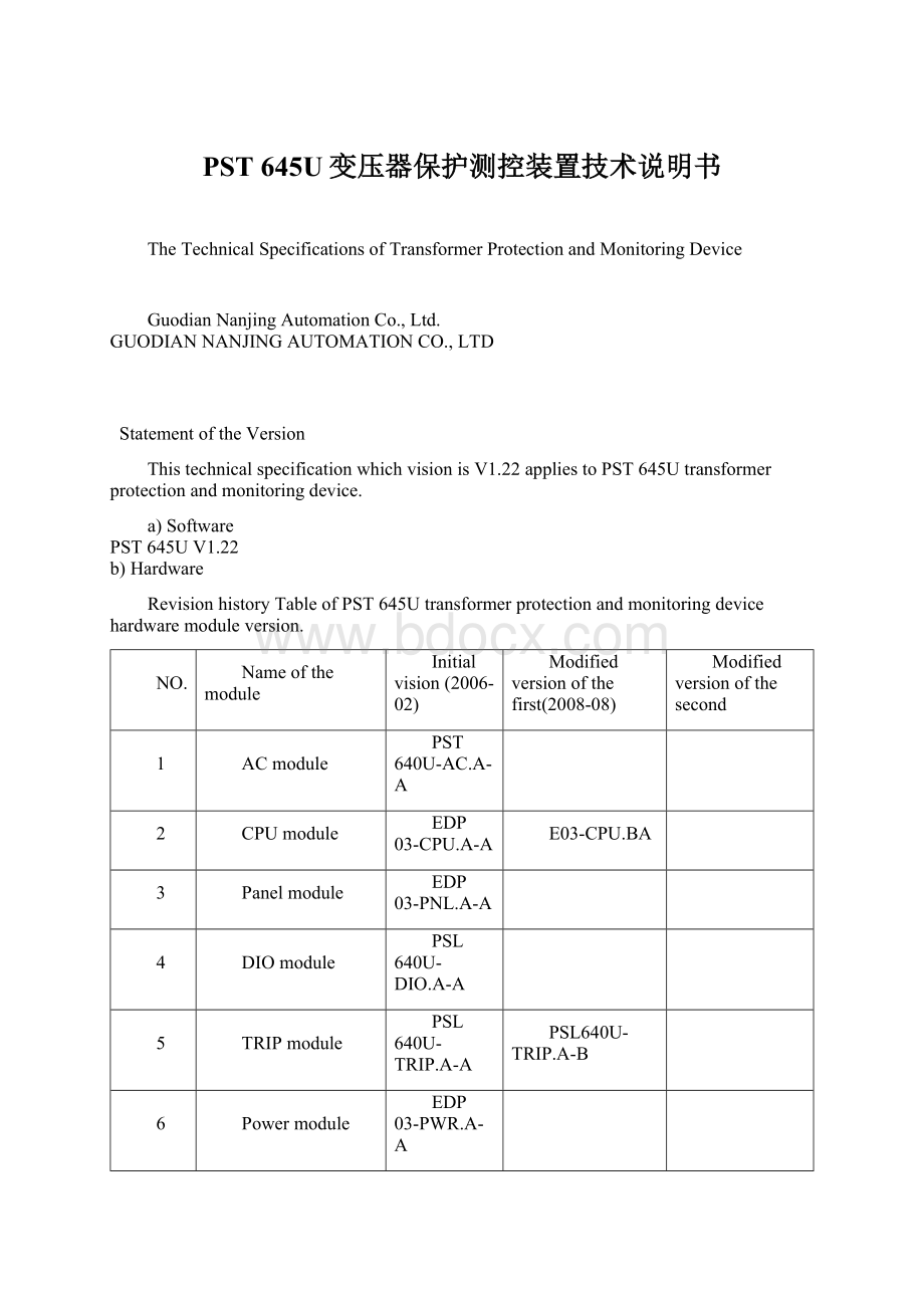
1
ACmodule
PST640U-AC.A-A
2
CPUmodule
EDP03-CPU.A-A
E03-CPU.BA
3
Panelmodule
EDP03-PNL.A-A
4
DIOmodule
PSL640U-DIO.A-A
5
TRIPmodule
PSL640U-TRIP.A-A
PSL640U-TRIP.A-B
6
Powermodule
EDP03-PWR.A-A
7
Basismodule
EDP03-MB.A-A
8
Communicationmodule
EDP03-COM.B-A
9
Clocksynchronizationmodule
EDP03-CLK.A-A
RevisionhistoryTableofPST645Utransformerprotectionandmonitoringdeviceproductinstruction.
10
V1.22
V1.10
V1.00
ManualVersionNumber
ModifiedAbstract
Directory
VersionoftheStatement
1.Outline............................................................................................................................1
1.1.Protectionfunctionsettings......................................................................................1
1.2.Monitoringandcontrollingfunctionsettings...........................................................1
2.Technicalparameters....................................................................................................2
2.1.Precisescopeofworkonprotectioncomponents....................................................2
2.2.Settingerroronprotectioncomponents...................................................................2
2.3.Protectionoftheentiresetofactiontime.................................................................2
2.4.Technicalparametersofmeasurementandcontrolfunctions...................................2
3.Protectionfunctionandprinciple...............................................................................3
3.1.Phaseover-currentprotection...................................................................................3
3.1.1Low-voltageblockingelements............................................................................3
3.1.2Negativesequenceovervoltageblockingelements..............................................3
3.1.3Whitecurrentinversetimeprotection..................................................................3
3.2.Overloadprotection..................................................................................................4
3.3.Zerosequenceover-currentprotection.....................................................................4
3.4.Zerosequenceovervoltageprotection.....................................................................4
3.5.Low-voltageprotection............................................................................................4
3.6.Acceleration.............................................................................................................4
3.7Non-powerprotection...............................................................................................4
3.8Trippinglogicmatrix................................................................................................5
3.9TVbreak...................................................................................................................5
4.TerminalDescription....................................................................................................6
4.1.Totalterminalplans..................................................................................................6
4.2.ACmoduleterminaldefinitionofX1......................................................................6
4.3.CPUmoduleterminaldefinitionofX2....................................................................7
4.4DIOmoduleterminaldefinitionofX3......................................................................8
4.5DIOmoduleterminaldefinitionofX4......................................................................8
4.6TRIPmoduleterminaldefinitionofX5.....................................................................8
4.7TRIPmoduleterminaldefinitionofX6.....................................................................9
5.Setpointtuninginstructions.........................................................................................10
5.1Listandinstructionofprotectionvalue....................................................................10
5.2Listandinstructionofoperatingparameters...........................................................12
5.3ListandinstructionofSoftplaten...........................................................................12
6.Deviceinformationcodetable.....................................................................................14
6.1Eventinformationtable.............................................................................................14
6.2Alarminformationtable............................................................................................14
6.3Softplateninformationtable.....................................................................................15
6.4RemoteCommunicationinformationtable...............................................................15
6.5Remotemeasurementinformationtable....................................................................16
6.6Remotecontrollinginformationtable......................................................................16
7.Deviceofsecondarywiringdiagram............................................................................18
1.Outline
PST645Utransformerprotectionandmonitoringdeviceappliestothenon-directgroundingsystemorlowresistancegroundingstationwhichvoltagelevelisbelow110KV.Itcanbescreenedorinstalledgrounding.
1.1Protectivefunctionconfiguration
1)threesectionsofthecompositevoltagelockoutover-currentprotection(IIIsegmentcanbesettotheinversetime)
2)Thethreesectionsofhigh-pressuresideofthezero-sequenceover-currentprotection(IIIsegmentalarm/tripoption)
3)Thethreesectionsthelowpressuresideofthezero-sequenceover-currentprotection(IIIsegmentcanbesettotheinversetime)
4)overload(alarm/tripoption)
5)zerosequenceovervoltageprotection(alarm/tripoption)
6)Lowvoltageprotection
7)Handaccelerateprotection
8)4-waynon-powerprotection
1.2monitoringandcontrollingfunctionsconfiguration
1)22-wayexternalswitchinputandtele-signalcollection;
2)Thecircuitbreakerposition,manualswitchingaccidenttele-signalcollection;
3)normalbreakerwhichswitchingisremote;
4)2pulseinput,accumulatedelectrical;
5)timeofGPSisadaptivewheninput.
2Technicalparameters
2.1preciseworkingscopeorprotectionofcomponentsVoltage:
1.0V~150.0V;
Current:
0.04IN~20IN;
ZeroSequenceCurrent:
0.02A~12.0A.
Note:
INtherating,thesamebelow.
2.2Protectionelementsettingerror
Currentcomponents:
≤±
2.5%or±
0.01IN;
Thevoltageelement:
0.005UN;
Thetimeelement:
definitetime≤(%1settingvalue)+40ms.
Voltageisrating,thesamebelow.
2.3protectingtheentiregroupofactiontime
Instantaneoustripcurrent:
1.5timesofthesettingvalueisnotgreaterthan40ms.
2.4Technicalparametersofmonitoringandcontrollingfunctions
RefertoPS640Useriesprotectionandmonitoringdevicemanual
3.Protectionfunctionandprinciple
3.1phaseover-currentprotection
Deviceintheimplementationofthethree-stagecross-flowdiscriminantislogicallyconsistentanditsoperationconditionsareasfollows:
1)Iφ>
Idn;
Idnisthecurrentsettingofthensegment;
Iφisphasecurrent;
2)T>
Tdn;
Tdnisthedelayingvalueofthensegment.
Itslowpressureblockingelementandnegativesequencevoltageblockingelementisdecidedaccordingtocontrollingword.
3.1.1Lowvoltagelockoutelement
Actionwhenanyoneofthelowvoltagecomponentsinthethreelinevoltagebelowthelowvoltagesetpoint,theopenlatchprotectionelement.Usingthiscomponent,youcanguaranteethatthedevicedoesnotappearinthecaseofnon-faultmotorfeedbackmalfunction.
3.1.2Negativesequenceovervoltagelockoutcomponents
Whennegativesequencegreaterthanthenegativesequenceovervoltagesetting,openlockoutprotectioncomponents.Togetherconstitutethethecompositevoltageblockingelement,withlowvoltageblockingelementwithover-currentelementsconstitutethecompositevoltageover-currentprotection.
3.1.3phasecurrentinversetimeelement
Inversetimeprotectioncomponentsizenaturallywiththeactiontimelimitprotectioncircuitcurrentprotectiondevices,bypanningactioncurve,youcanveryeasilywithacrosstheboard.Thedeviceprovidesthecommoncharacteristicsofthethreetypesofinversetime,thatisthestandardinverse,veryinverse,extremelyinverseandinverse-timecharacteristicsbysettingthevalueofthecorrespondinginversetimeindextuning.Inversetimecharacteristicsofthefollowingformula:
1)Normalinverse
2)Veryinversetime
3)ExtremelyInverse
:
tpisthetimecoefficient,andtherangeisfrom0.05to1;
IPisacurrentreferencevalue;
Iisafaultcurrent;
tisthetrippingtime.
Inversetimethevalueoftheportionofthetuningforthevalueoftheproductofthemoleculesintheabov
 升级会员
升级会员 