基于C51兼容微处理器单片机的PWM控制器设计.docx
《基于C51兼容微处理器单片机的PWM控制器设计.docx》由会员分享,可在线阅读,更多相关《基于C51兼容微处理器单片机的PWM控制器设计.docx(10页珍藏版)》请在冰豆网上搜索。
基于C51兼容微处理器单片机的PWM控制器设计
基于C51兼容微处理器单片机的PWM控制器设计
——外文翻译
英文原文
DesignofPWMControllerinaMCS-51CompatibleMCU
Author.Yue-LiHu,WeiWangMicroelectronicResearch&DevelopmentCenter
CampusP.O.B.221,149YanchangRd,Shanghai200072,China
Introduction
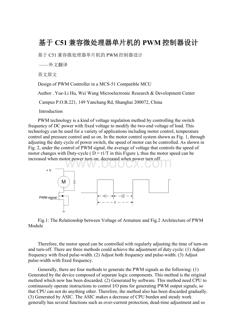
PWMtechnologyisakindofvoltageregulationmethodbycontrollingtheswitchfrequencyofDCpowerwithfixedvoltagetomodifythetwo-endvoltageofload.Thistechnologycanbeusedforavarietyofapplicationsincludingmotorcontrol,temperaturecontrolandpressurecontrolandsoon.InthemotorcontrolsystemshownasFig.1,throughadjustingthedutycycleofpowerswitch,thespeedofmotorcanbecontrolled.AsshowninFig.2,underthecontrolofPWMsignal,theaverageofvoltagethatcontrolsthespeedofmotorchangeswithDuty-cycle(D=t1/TinthisFigure),thusthemotorspeedcanbeincreasedwhenmotorpowerturnon,decreasedwhenpowerturnoff.
Fig.1:
TheRelationshipbetweenVoltageofArmatureandFig.2ArchitectureofPWMModule
Therefore,themotorspeedcanbecontrolledwithregularlyadjustingthetimeofturn-onandturn-off.Therearethreemethodscouldachievetheadjustmentofdutycycle:
(1)Adjustfrequencywithfixedpulse-width.
(2)Adjustbothfrequencyandpulse-width.(3)Adjustpulse-widthwithfixedfrequency.
Generally,therearefourmethodstogeneratethePWMsignalsasthefollowing:
(1)Generatedbythedevicecomposedofseparatelogiccomponents.Thismethodistheoriginalmethodwhichnowhasbeendiscarded.
(2)Generatedbysoftware.ThismethodneedCPUtocontinuouslyoperateinstructionstocontrolI/OpinsforgeneratingPWMoutputsignals,sothatCPUcannotdoanythingother.Therefore,themethodalsohasbeendiscardedgradually.(3)GeneratedbyASIC.TheASICmakesadecreaseofCPUburdenandsteadyworkgenerallyhasseveralfunctionssuchasover-currentprotection,dead-timeadjustmentandsoon.Thenthemethodhasbeenwidelyusedinmanykindsofoccasionnow.(4)GeneratedbyPWMfunctionmoduleofMCU.ThroughembeddingPWMfunctionmoduleinMCUandinitializingthefunction,PWMpinsofMCUcanalsoautomaticallygeneratePWMoutsignalswithoutCPUcontrollingonlywhenneedtochangeduty-cycle.Itisthemethodthatwillbeimplementedinthispaper.
Inthispaper,weproposeaPWMmoduleembeddedina8051microcontroller.ThePWMmodulecansupportPWMpulsesignalsbyinitializingthecontrolregisterandduty-cycleregisterwiththreemethodsjustmentionedabovetoadjustthedutycycleandseveraloperationmodestoaddflexibilityforuser.
ThefollowingsectionexplainsthearchitectureofthePWMmoduleandthearchitecturesofbasicfunctionalblocks.Section3describestwooperationmodes.Experimentalandsimulationresultsverifyingpropersystemoperationarealsoshowninthatsection.Dependingonmodeofoperation,thePWMmodulecreatesoneormorepulse-widthmodulatedsignals,whosedutyratioscanbeindependentlyadjusted.
ImplementationofPWMmoduleinMCU
OverviewofthePWMmodule
AblockdiagramofPWMmoduleisshowninFig.3.Itisclearlyfromthediagramthatthewholemoduleiscomposedoftwosections:
PWMsignalgeneratoranddead-timegeneratorwithchannelselectlogic.ThePWMfunctioncanbestartedbytheuserthroughimplementingsomeinstructionsforinitializingthePWMmodule.Inparticular,thefollowingpowerandmotioncontrolapplicationsaresupported:
•DCMotor
•UninterruptablelPowerSupply(UPS)
·ThePWMmodulealsohasthefollowingfeatures:
•TwoPWMsignaloutputswithcomplementaryorindependentoperation
•Hardwaredead-timegeneratorsforcomplementarymode
•DutycycleupdatesareconfigurabletobeimmediatedorsynchronizedtothePWM
Fig.3ArchitectureofPWMModule
Detailsofthearchitecture
PMWgenerator
Thearchitectureofthe2-outputPWMgeneratorshowninFig.4isbasedona16-bitresolutioncounterwhichcreatesapulse-widthmodulatedsignal.Thesystemissynthesizedbyasystemclocksignalwhosefrequencycanbedividedby4timesor12timesthroughsettingthevalueofT3MforPWM0orT4MforPWM1inthespecialregisterPWMCONasshowninFig.4.ToPWM0generator,theclockto16-bitcounterwillbepre-dividedby4timesbydefaultwhenT3Missettozero.Andtheclockwillbedividedby12timeswhenT3Missetto1.ThisisalsotrueforPWM1.TheotherbitsinPWMCONareexplainedindetailinTable1.
Fig.4BitMappingofPWMCON
Table1:
TheBitDefinitioninPWMCON
Channel-selectlogic
ThefollowFig.5showsthechannel-selectlogicwhichisusefulinComplementaryMode.Fromthisdiagram,itiscleartoknowthatsignalCPandCPWMcontrolthesourceofPWMHandPWML.Andthedetailsaboutthetwocontrolsignalswillbediscussedinthesection3,andthearchitectureofdead-timegeneratorwillalsobediscussedinsection5for
 升级会员
升级会员 