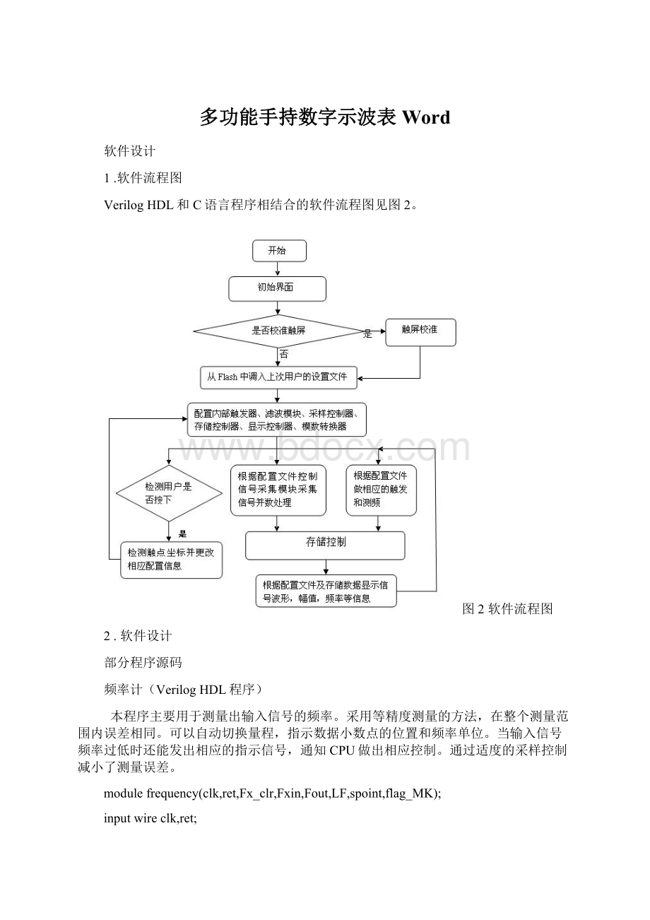
多功能手持数字示波表WordWord文档格式.docx
《多功能手持数字示波表WordWord文档格式.docx》由会员分享,可在线阅读,更多相关《多功能手持数字示波表WordWord文档格式.docx(26页珍藏版)》请在冰豆网上搜索。

0]spoint;
//指示小数点的位置
0]flag_MK;
//频率单位:
M标志K标志
wireFx_cph;
reg[7:
0]cp_ch;
regFend;
//测频结束标志
regFsst;
//控制本地标频开始计数的标志0:
开始计数
reg[39:
0]Ns;
//对本地标频的计数
reg[23:
0]LFCH;
//低频检测计数器,对底频率和直流做出警报和指示
reg[15:
0]Nx,Nx1;
//对待测频率的计数,Nx1检测低频被测信号的暂存器
regs0,s1,s2,s3,s4,s5,s6,s7,s8,sx1000;
always@(posedgeclkornegedgeret)
if(!
ret)
begin
sx1000<
=1'
b0;
s0<
s1<
s2<
s3<
s4<
s5<
s6<
s7<
s8<
end
else
=(Nx>
=1000);
=(Ns==40'
d100_0);
d100_00);
d100_000);
d100_000_0);
d100_000_00);
d100_000_000);
d100_000_000_0);
d100_000_000_00);
=(Ns>
=40'
d100_000_000_000);
Fend<
flag_MK<
=2'
b00;
spoint<
Fout<
=16'
h0000;
if(Fend)Fend<
if(Fx_clr)Fend<
b1;
if(sx1000)
case({s0,s1,s2,s3,s4,s5,s6,s7,s8})//--F-sp-MK
9'
b10_0000_000:
{Fout,Fend,spoint,flag_MK}<
={Nx,5'
b1_01_10};
b01_0000_000:
b1_10_10};
b00_1000_000:
b1_11_10};
b00_0100_000:
b1_01_01};
b00_0010_000:
b1_10_01};
b00_0001_000:
b1_11_01};
b00_0000_100:
b1_01_00};
b00_0000_010:
b1_10_00};
b00_0000_001:
b1_11_00};
endcase
always@(posedgeclkorposedgeFend)
if(Fend)
LFCH<
=24'
h000000;
LF<
=LFCH+1'
if(LFCH==24'
d100_000_00)beginLF<
=(Nx1==Nx);
d0)Nx1<
=Nx;
ret)Fsst<
elseif(Fx_cph)Fsst<
=!
Fend;
//边沿对齐
if(Fend)Ns<
h0000000000;
elseif(Fsst)Ns<
=Ns+1'
assignFx_cph=(cp_ch==8'
b11110000);
if(Fend)cp_ch<
elsecp_ch<
={cp_ch[7:
0],Fxin};
always@(posedgeclkorposedgeFend)
if(Fend)Nx<
elseif(Fx_cph)Nx<
=Nx+1'
endmodule
6.3.2LCD控制器(VerilogHDL程序)
主要用于转换控制液晶的协议,加快CPU的写入和控制,可以做到两时钟并行周期访问。
内部有的PWM模块用于控制液晶的显示亮度,CPU只需要向相应的寄存器写入亮度控制数就能控制液晶的亮度。
moduleTFT_LCD_IP(
//ClcokInput时钟和复位
inputcsi_clk,
inputcsi_reset_n,
//Avalon-MMSlave总线的连接
inputavs_chipselect,
input[8:
0]avs_address,//[RS],[A2],[A1],[A0]
//3-----2----1----0位
inputavs_write,
input[31:
0]avs_writedata,
inputavs_read,
output[31:
0]avs_readdata,
//ip_TFT液晶的接口
output[15:
0]coe_lcd_data,
outputcoe_lcd_cs,
outputcoe_lcd_rs,
outputcoe_lcd_wr,
outputregcoe_lcd_pwm,
outputregcoe_lcd_res,
inputcoe_touch_int,
inputcoe_touch_dout,
outputregcoe_touch_din,
outputregcoe_touch_busy,
outputregcoe_touch_dclk,
outputregcoe_touch_cs
);
regdiv_se;
reg[19:
0]div_buf;
//PWM的前置分频寄存器
reg[2:
0]count;
//脉频计数器
0]pwm_buf;
//占空比(0~7)
reg[31:
0]read_data;
//总线从外界读取的数据寄存器
wirecheck;
//中间检测信号
wireall_cs;
assignall_cs=(avs_address[7:
0]==8'
h00);
//writetoip_TFTformNiosIIcpu
assigncheck=avs_write&
all_cs;
assigncoe_lcd_wr=check?
1'
b1:
1'
assigncoe_lcd_cs=(avs_chipselect&
all_cs)?
b0:
assigncoe_lcd_rs=avs_address[8];
assigncoe_lcd_data=(avs_chipselect&
avs_writedata[15:
0]:
16'
hzzzz;
//使用一个时钟读取时,触摸板能读出正常数据,但是出现闪屏
assignavs_readdata=read_data;
always@(negedgecsi_clkornegedgecsi_reset_n)
begin
if(!
csi_reset_n)
pwm_buf<
=3'
b111;
coe_lcd_res<
coe_touch_din<
coe_touch_busy<
coe_touch_dclk<
coe_touch_cs<
elseif(avs_chipselect&
(!
all_cs))
begin
case(avs_address[7:
0])
8'
b0000_0001:
pwm_buf<
=avs_writedata[2:
0];
b0000_0010:
coe_lcd_res<
=avs_writedata[0];
b0000_0100:
coe_touch_din<
=avs_writedata[0];
b0000_1000:
coe_touch_busy<
b0001_0000:
coe_touch_dclk<
b0010_0000:
coe_touch_cs<
b0100_0000:
read_data[0]<
=coe_touch_int;
b1000_0000:
=coe_touch_dout;
end
always@(posedgecsi_clkornegedgecsi_reset_n)
csi_reset_n)
begindiv_buf<
=20'
h00000;
div_se<
else
if(div_buf==20'
d100000)
h00