网络组建课程设计.docx
《网络组建课程设计.docx》由会员分享,可在线阅读,更多相关《网络组建课程设计.docx(14页珍藏版)》请在冰豆网上搜索。
网络组建课程设计
课程设计
班级:
学号:
姓名:
任课教师:
设计题目:
\(^o^)/YES!
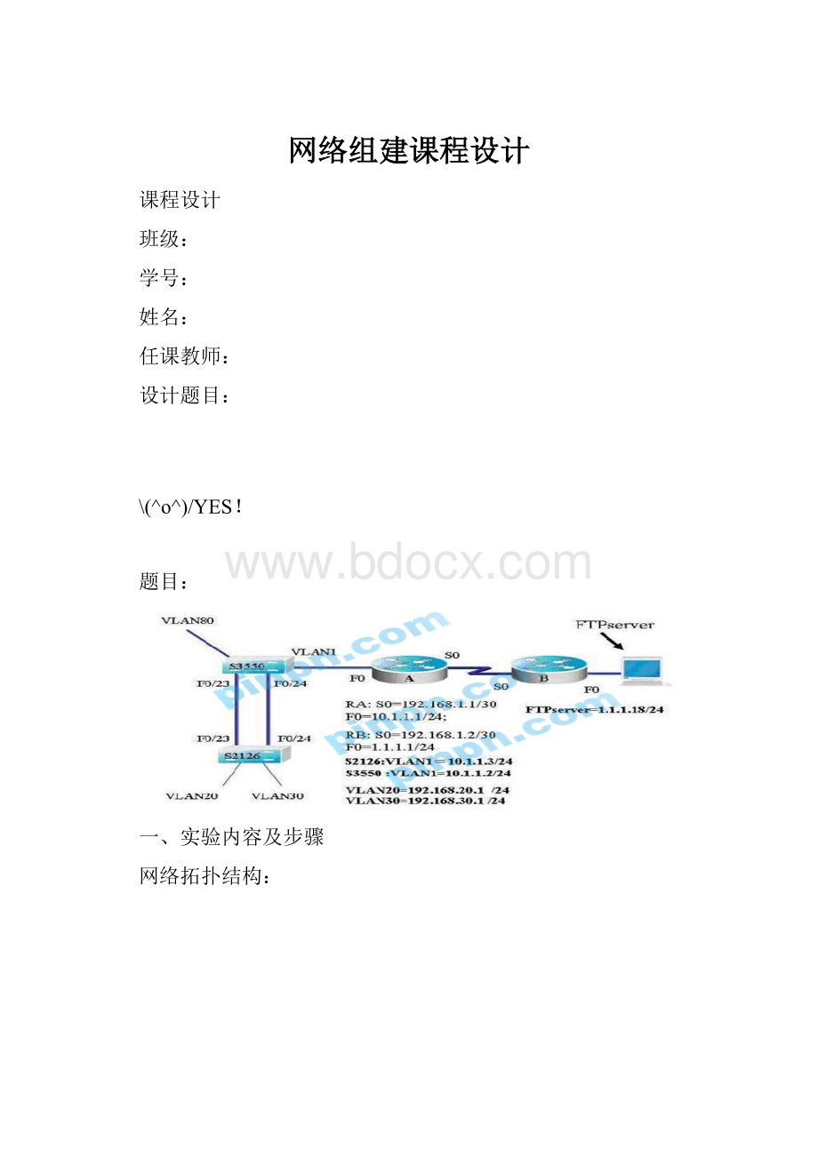
题目:
一、实验内容及步骤
网络拓扑结构:
1、 配置全网四台设备,使四台设备均能远程管理,为了安全起见,特权密码不能明文显示
Switch>
Switch>en!
进入特权模式
Switch#conft!
进入全局配置模式
Switch(config)#hostnames2!
改名
s2(config)#enablesecretlevel150star!
设置特权密码为0
s2(config)#enablesecretlevel10star
s2(config)#intvlan1!
创建虚拟接口vlan1
s2(config-if)#ipadd10.1.1.3255.255.255.0!
配置ip10.1.1..3/24
s2(config-if)#noshutdown
Switch>en
Switch#conft!
进入全局配置模式
Switch(config)#hostns3!
改名
s3(config)#enabsecretlevel150star!
设置特权密码为0
s3(config)#enabsecretlevel10star
s3(config)#intvl1!
创建虚拟接口vlan1
s3(config-if)#ipadd10.1.1.2255.255.255.0!
配置ip10.1.1..3/24
s3(config-if)#noshutdown
Router>en
Router#conft!
进入全局配置模式
Router(config)#hostnameR1!
改名
R1(config)#enablesecretstar
R1(config)#linevty04!
进入远程管理线程
R1(config-line)#passwordstar!
输入远程管理线程密码star
R1(config-line)#intf0/0!
进入接口f0/0
R1(config-if)#ipadd10.1.1.1255.255.255.0!
配置ip10.1.1.1/24
R1(config-if)#noshutdown
R1(config-if)#exit
R1(config)#ints0/0!
进入接口s0/0
R1(config)#ints0/0/0!
进入接口s0/0/0
R1(config-if)#ipadd192.168.1.1255.255.255.0!
配置ip192.168.1.1/24
R1(config-if)#ipadd192.168.1.1255.255.255.240!
配置ip192.168.1.1/28
R1(config-if)#clockrate64000!
在DEC接口上配置时钟频率64000
R1(config-if)#noshutdown
Router>en
Router#conft!
进入全局配置模式
Router(config)#hostnameR2!
改名
R2(config)#enabsecstar!
设置特权模式密码为star
R2(config)#linevty04!
进入远程管理线程
R2(config-line)#passwordstar!
输入远程管理线程密码star
R2(config-line)#intf0/0!
进入接口f0/0
R2(config-if)#ipadd1.1.1.1255.255.255.0!
配置ip1.1.1.1/24
R2(config-if)#noshutdown
2、 S3550与S2126两台设备创建相应的VLAN,S2126VLAN20包含1-5及8端口,S2126VLAN30包含10-15端口。
S3550VLAN80的接口为F0/7
s2(config)#vl20!
启用vlan20
s2(config-vlan)#intrangef0/1-5,f0/8!
进入端口
s2(config-if-range)#switchportaccessvlan20!
端口划分vlan
s2(config-if-range)#exit
s2(config)#vl30
s2(config-vlan)#exit
s2(config)#intrangef0/10-15
s2(config-if-range)#switchportaccessvlan30
s3(config)#vl80!
启用vlan80
s3(config-vlan)#exit
s3(config)#intrangef0/7!
进入端口
s3(config-if-range)#switchportaccessvlan80!
端口划分vlan
3、 S3550与S2126两台设备F0/1与F0/2接口作为TRUNK端口,建立TRUNK链路
s2config)#interfacerangefa0/1-2
s2(config-if-range)#switchportmodetrunk!
把该端口设为trunk口
s3(config)#interfacerangefa0/1-2
s3(config-if-range)#switchportmodetrunk!
把该端口设为trunk口
4、 S3550与S2126两台设备运行802.3ad(聚合端口),实现链路的负载均衡。
S2(config)#intrangef0/5-6!
进入端口
S2(config)#channel-group1!
聚合端口
S3(config)#intrangef0/5-6!
进入端口
S3(config)#channel-group1!
聚合端口
5、 在S3550上做相应配置,使得所有VLAN间可以互相访问,并且和RA可以互通。
s30#en
s30#conft
s3(config)#intvlan20!
打开交换机的vlan20
s3(config-if)#ipadd192.168.20.1255.255.255.0!
为vlan20接口分配ip地址
s3(config-if)#noshutdown!
开启接口工作状态
s3(config-if)#exit
s3(config)#intvlan30
s3(config-if)#ipadd192.168.30.1255.255.255.0
s3(config-if)#noshutdown
s3(config-if)#exit
s3(config)#intvlan80
s3550(config-if)#ipadd192.168.80.1255.255.255.0
s3550(config-if)#noshutdown
6、在S2126上设置F0/5端口为安全端口,该端口下最大地址个数为5,设置违例方式为shutdown
S2(config)#intf0/5
S2(config-if)#switchportport-securitymaximum5!
限制此端口允许通过的mac安全地址数为5
s2(config-if)#switchportport-securityviolationshutdown!
非安全地址通过时端口关闭
s2(config-if)#exit
7、分别在S3550、RA、RB上配置静态路由,实现全网互通。
R1(config)#iproute172.16.3.0255.255.255.0172.16.2.2!
配置到达非直连172.16.3.0网络的下一跳地址172.16.2.2
R2(config)#iproute172.16.1.0255.255.255.0172.16.2.1!
配置到达非直连172.16.1.0网络的下一跳地址172.16.2.1
8、 在路由器A作配置只允许办公网访问服务器的FTP服务,学生网不可以访问服务器。
R1(config)#acc
R1(config)#access-list101denyt
R1(config)#access-list101denytcp192.168.30.00.0.0.2551.1.1.80.0.0.255eqftp
R1(config)#intf0/1
R1(config-if)#intf0/0!
打开指定的接口
R1(config-if)#ipaccess-group101in!
ipaccess-group101in命令应用标识101访问控制列表,关键字in指明所控制的方向
R1(config-if)#exit
在S2126上运行:
showvlan:
Showipinterface;
Showspanning:
Showrunning-config
Showinterfacef0/23swITchport
Showinterfacef0/24switchport
在3550上要运行
showvlan
Showipinterface
Showspanning
Showrunning-config
Showiproute
在路由器A和B上运行
Showiproute
路由器A还要运行
showaccess-lists
二、实验结果
三、试验描述
通过svi配置使交换机与pc机之间ping通
四、课程设计总结
 升级会员
升级会员 