RSF16001300泥浆泵说明书英文.docx
《RSF16001300泥浆泵说明书英文.docx》由会员分享,可在线阅读,更多相关《RSF16001300泥浆泵说明书英文.docx(43页珍藏版)》请在冰豆网上搜索。
RSF16001300泥浆泵说明书英文
RS-F1600/1300MUDPUMP
OPERATION&MAINTENANCEMANUAL
RONGSHENGMACHINERYMANUFACTURELTD.OFHUABEIOILFIELD,HEBEI,CHINA
CONTENT
PREFACE
Thismanualisprovidedforguidanceofwhowishtomounting,repair,maintainoradjusttheRSF-1600MudPump.Thismanualcoversspecification,structurecharacter,mountingation,operationandmaintenance.Itisnotintended,norwoulditbepossibleinsuchlimitedspace,tocovereverypossiblecondition,whichmaybeencountered.
Inthismanual,thedirectionoffront,back,leftandrightistheviewfrompowerendtofluidend.
ChapterⅠMOUNTATION,OPERATIONANDMAINTENACE
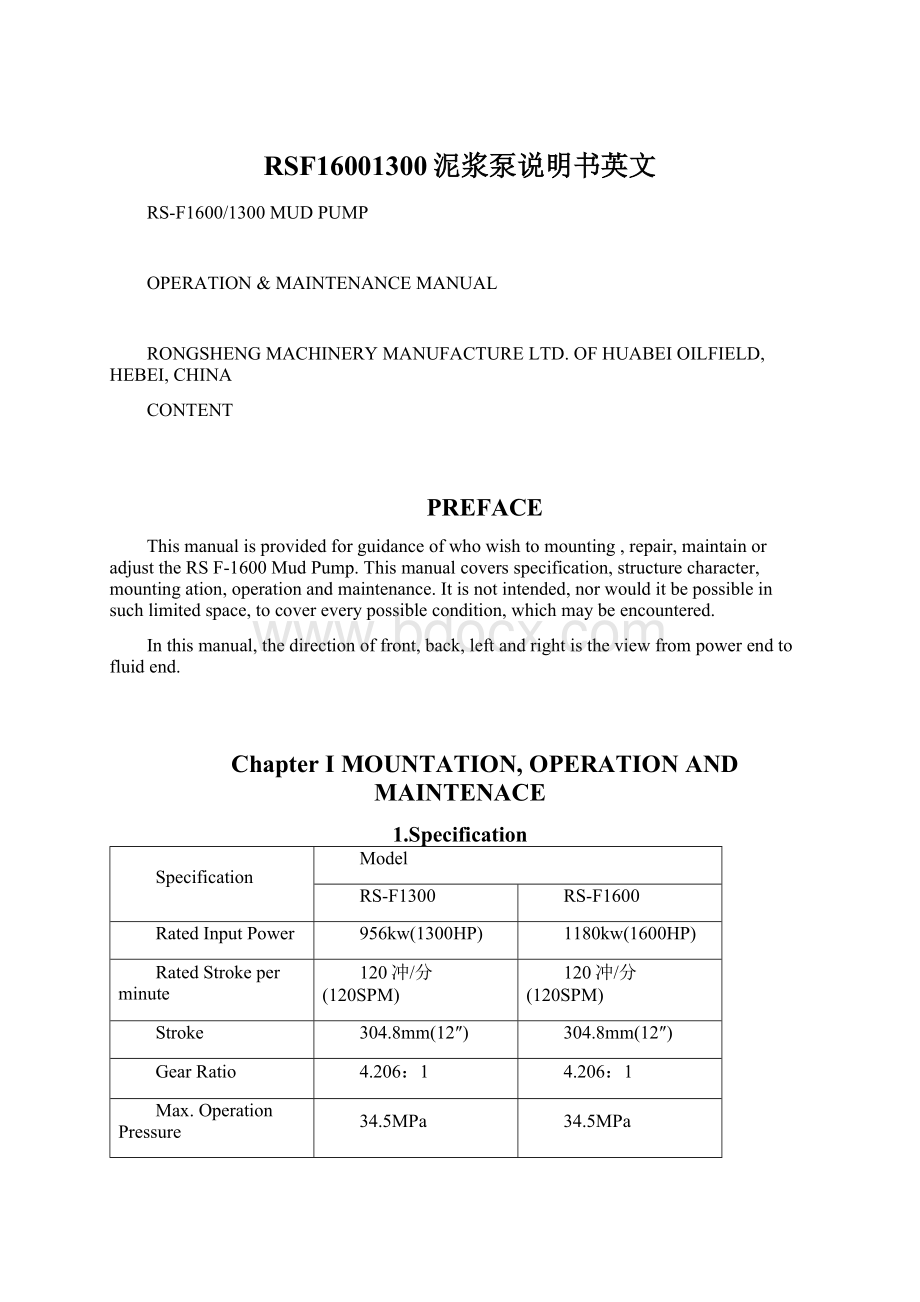
1.Specification
Specification
Model
RS-F1300
RS-F1600
RatedInputPower
956kw(1300HP)
1180kw(1600HP)
RatedStrokeperminute
120冲/分(120SPM)
120冲/分(120SPM)
Stroke
304.8mm(12″)
304.8mm(12″)
GearRatio
4.206:
1
4.206:
1
Max.OperationPressure
34.5MPa
34.5MPa
ValveChamber
API#7
API#7
Max.LinerDia.
7″
71/4″
Max.LinerMudPressure
18.5MPa
23.3MPa
Dia.OfSuctionManifold
305mm(12″)
305mm(12″)
Dia.OfDischargeManifold
51/8″flange(5000psi)
51/8″flange(5000psi)
Dia.OfPinionShaft
215.9mm(8.5″)
215.9mm(8.5″)
Key
50.8x50.8mm(2x2″)
50.8x50.8mm(2x2″)
OverallDimension
4684x2413x2063mm
4684x2413x2063mm
Weight(Mainbody)
24572kg
24751kg
RS-F1300Specification
LinerDia.in
7
63/4
61/2
61/4
6
51/2
5
DischargePressurePsi
2720
3050
3188
3440
3915
4495
5000
StrokeperMinute
InputPower
DischargeCapacity(L/S)
KW
HP
120
956
1300
45.41
42.22
39.15
36.20
33.36
28.03
23.17
110
874
1188
41.63
38.7
35.89
33.18
30.58
25.69
21.24
100
795
1081
37.84
35.18
32.63
30.17
27.8
23.36
19.31
90
715
972
34.06
31.67
29.36
27.15
25.02
21.02
13.38
50
397
540
18.92
17.59
16.31
15.08
13.9
11.68
9.65
1
79
107
0.3784
0.3518
0.3263
0.3017
0.278
0.2336
0.1931
RS-F1600SPECIFICATION
LinerDia.in
71/4
7
63/4
61/2
61/4
6
51/2
DischargePressurePsi
3146
3345
3750
3930
4235
4820
5000
StrokeperMinute
InletPower
DischargeCapacity(L/S)
kw
HP
120
1180
1600
48.71
45.41
42.22
39.15
36.20
33.36
28.03
110
1078
1462
44.65
41.63
38.7
35.89
33.18
30.58
25.69
100
980
1329
40.59
37.84
35.18
32.63
30.17
27.8
23.36
90
882
1196
36.53
34.06
31.67
29.36
27.15
25.02
21.02
50
490
664
20.29
18.92
17.59
16.31
15.08
13.9
11.68
1
98
133
0.406
0.3784
0.3518
0.3263
0.3017
0.278
0.2336
MechanicalEfficiencyη=90%,Fillfactorα=100%,VolumeEfficiency:
100%
2.StructureCharacter
2.1PowerEnd
2.1.1Frame
Frameisweldstructureandtransmissionshaft&bearingseatofcrankshaftarecaststeel.Afterroughmachined,itisweldedwiththeshell.Bearingseatofcrankshaftisstrengthenedwithribs.Annealtreatmentisadoptedtoreleaseweldstresstoimproverigidityandstrength.
2.1.2Crankshaft
Crankshaftiscastalloysteel.Largegearrim,pitmenandbearingsaremountedonthecrankshaft.Geartypeoflargegearrimisintegratedherringbone.Innerholeoflargegearrimandcrankareinterferencematch,andarefastenedwithbolts&locknuts.Largeendsofpitmenaremountedonthethreeeccentricaxilsofcrankshaftthroughsingle-rawshortcylindricalrollerbearings.Whilesmallendsaremountedonthecrossheadpinsthroughdoublerawlongcylindricalrollerbearings.Crankshaftissupportedbytwodoublerawannularballbearings.
2.1.1Pinionshaft
Pinionshaftisforgealloysteel.Thereisaherringbonegear,whichismiddlehardness.
Inordertoeasytorepair,singlerawlongcylindricalrollerbearingisadopted,whichisnobaffle.Thetwoendsofpinionshaftextendtooutsideoftheshellandpulleycanbemountedoneachendofit.
2.1.2Crosshead
Crossheadissphericalgraphitecastironandhasgoodwearresistanceperformanceto
realizelongerusagelife.Topandbottomguideplateareadoptedinmudpump,andconcentricitycanbeadjustedthroughbottomplateplusspacer.Connectionbetweencrossheadandcentralpullrodisflangedwhichispinmatchedhole.Thisrigidconnectioncanensureconcentricitybetweencentralrodandcrosshead.Thecentralrodisconnectedwithpistonrodthroughhubandthislighthubcanensurereliableconnectionbetweenthem.
2.2FluidEnd
2.2.1Cylinder
Cylinderisforgedbyalloysteelandthethreecylindersonmudpumpcanbeexchanged.Thoroughstructuredesign,whichisvalveonvalve,canreducecylindervolumeandtoimprovevolumeefficiency.Cylindersurfacecancoatednickeltoimproveitscorrosionresistanceperformanceifclientsrequire.Dischargecompressor,shearpinsafetyvalveanddischargefilterscreenaremountedoneachdischargeoutletofthreecylinders.Dischargeoutletis51/8″5000psiflange
2.2.2ValveAssy.
API7#valveisusedbothforF-1600&F-1300mudpump.Suctionvalveanddischargevalvecanalsobeexchanged.
2.2.2Liner
Linercanbeprocessedwithdoublemetallayerwhichinnerlayeriswearresistancecast
ironwithhardnessHRC60~65,alsohasgoodcorrosionresistanceperformanceandfinish。
2.2.3Pistonandpistonrod
Pistonandpistonrodissealedthroughcylindersurfaceandrubberring.Locknutsareusedtopreventpistonloosenandseal.
2.2.5SpraySystem
Spraysystemincludesspraypump,cooldownwatertankandspraypipe.Itisusedtocoolandwashlinerandpistontoimprovetheirusagelife.
Spraypumpiscentrifugepumpandcanbedriventhroughbeltwhichpulleyismountedontheextendendoftheinletshaftorelectricalmotordirectly.Waterisadoptedtocoolandlubricateit.
Spraypipeismountedonthehubwhichconnectsmiddlepullrodandpistonrod,andcanmovereciprocallytogetherwithpiston.Coolfluidcanalwaysspraythecontactsurfacebetweenpistonandcylinderbecausenozzleisverynearpiston.Stationaryspraypipecanalsobeadoptedandhaslongusagelife.
2.2.6LubricationSystem
Pressurelubricationcombiningsplashlubricationisadoptedforpowerend.Pressureoilpumpedbygearoilpumpintheoiltankistransmittedtocrosshead,middlepullrod,crossheadguideandbearingsthroughlubricationpipeline.Workingconditionofgearoilpumpcanbewatchedfrompressuregaugeinthebackoftheshell.
2.2.7SuctionSystem
Suctionsystemisusedforpreventingairblockduetolowairpressureofpumpinlet.Suctionsystemiscomposedbybase,butterflyvalveandmanifold.Suctionpumponthesuctionmanifoldcanbedrivenbyelectricalmotororbybeltontheinletshaftofmudpumptoreducepowerconsumption.
3.Mountationofnewpump
3.1Mountationofpump
Inordertosavetimeandpower,beforemountingthispump,youshouldgivethecorrectprogramforlocatingthedrillingpump,spraypump,suctionpipeanddischargepipeline,includingtheredirection.
Theboxtypeconstructionofthepowerframehashighresistancetobendingbutrelativelylessresistanceagainsttwist.Therefore,thesupportunderthepumpmustbelevelandadequatetosupporttheweightandoperatingforcesexertedbythepump.Youshouldplacethepumponthelevelconcretefoundation,soastogetthecorrectlubricatingforpowerendandpreventpossibilityoftwistinganddistortingofpowerframe.
Onpermanentmountationsoronbarge,youmustlevelthepump,ensurethebaseofpumpbeinguniformsupported.Pleasedonottightthefoundationboltsunevenly,orunnecessarydistortionwillberesultedinthebaseofpump,andthatwilleffecttheoperatingofthepump.Ifyouusev-belttodrive,youshouldtofixthepumpbysteelboardandsupportrod,preventthepumpbeingmovedbytheforceexertedwiththev-belt.
3.1.1Mountationofthedrive
Thedrivebetweenthemudpumpsandthepowersource,whetherV-beltsormultiwidthchains,shouldbemountedwiththegreatestcaretoassuremaximumoperatinglifewithminimumofunexpectedorundesirableshutdownsduetodrivefailures.
Thesheavecanbemountedontheleftorrightsideaccordingtotherequirement.Therefore,wecanmountthesheaveusedfordrivingspraypumpontheothersideofthedrivingshaft.
Whenmountingthedrivesheave,makesureallgreaseofrustpreventativeisremovedfromtheshaftandtheboreofthedrive.Removeallburrsorroughspotsfromtheshaftend,key,andkeyway.Fitkeytothekeywaysintheshaftandthenmountingkeyintoshaftkeyway.
Coatdrivepinionshaftendwithlightoiloranti-seizecompoundandmountingthedrivesheavehub,thentightenthehubbolts,ThetighteningtorqueforRS-F1600/1300pumpisintableI.Whenmountingthehub,thetighteningforceontheboltsismultipliedmanytimesbythewedgingactionofthetaperedsurface.Thisactioncompressesthehubforasnugfitontheshaft.Ifthetightenboltsforceistoolarge,theburstingpressureiscreatedinthehubofthemountedpulleyandthispressuremaycausethepulleytocrack.Thehubboltsshouldalwaysbetightenedalternatelyandprogressively.
ChartI
Model
Tighteningtorque
N.m
Wrenchlengthmm
Force
N
F-1600/1300
813
900
900
Notice:
1N=0.1kg
3.1.2Checkbeforemountation
1)Checksheavegroovecondition.
Beforemountingthev-beltssheave,checksheavegroovesforwear.Wormorroundedgrooveswilldestroyv-beltsrapidly.Thesidewallsmustbestraight.Sheavegroovesmustbefreeofdirt,rustorotherextrusions,whichcoulddamagethev-belts.
2)Checksheavealignment.
Thefinalalignmentofthev-beltsheavesshouldbecheckedafterthev-beltshavebeenmountedandadjustedtotheiroperatingtension.Ifthesidesofthesheavesareofequaldistancefromthecenterlineofthegroove,checkalignmentbystretchingtwostrings(fishlineorpianowire
 升级会员
升级会员 