东南大学计算机系接口实验报告样板.docx
《东南大学计算机系接口实验报告样板.docx》由会员分享,可在线阅读,更多相关《东南大学计算机系接口实验报告样板.docx(36页珍藏版)》请在冰豆网上搜索。
东南大学计算机系接口实验报告样板
东南大学
接口实验报告
0900611009006111
2008-12-17
实验2-1
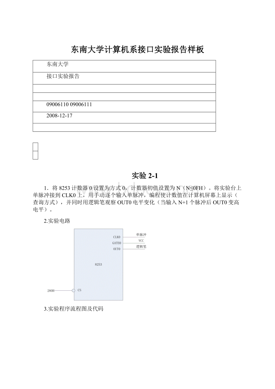
1.将8253计数器0设置为方式0,计数器初值设置为N(N≤0FH)。
将实验台上单脉冲接到CLK0上,用手动逐个输入单脉冲,编程使计数值在计算机屏幕上显示(查询方式),并同时用逻辑笔观察OUT0电平变化(当输入N+1个脉冲后OUT0变高电平)。
2.实验电路
3.实验程序流程图及代码
#include
#include
#include"ApiEx.h"
#pragmacomment(lib,"ApiEx.lib")
voidmain()
{
BYTEdata;
printf("----------EXP2_1-----------\n");
printf("Pressanykeytobegin!
\n\n");
getch();
printf("Pressanykeytoexit!
\n");
if(!
Startup())
{
printf("ERROR:
OpenDeviceError!
\n");
return;
}
//8253片选地址为0x280
PortWriteByte(0x283,0x10);//给计算器0写控制字00010000B=10H
PortWriteByte(0x280,0x0A);//计算器0置初值0AH
while(!
kbhit())//判断是否有键按下
{
PortReadByte(0x280,&data);//读计数器0的值
Sleep(1000);//延迟一秒钟
printf("%d\n",data);
}
Cleanup();
}
实验2-2
1.将计数器0,计数器1分别设置为方式3,利用这两个计数器,将实验台上的一个1MHz的方波信号分频为1Hz的方波(做好8253初始化工作),并将此方波接到L7上,观察L7以周期为1秒的频率闪烁。
2.实验电路
3.实验程序流程图及代码
#include
#include
#include"ApiEx.h"
#pragmacomment(lib,"ApiEx.lib")
voidmain()
{
printf("----------EXP2_2-----------\n");
printf("Pressanykeytobegin!
\n");
getch();
printf("Pressanykeytoexit!
\n");
if(!
Startup())
{
printf("ERROR:
OpenDeviceError!
\n");
return;
}
//8253片选地址280H
PortWriteByte(0x283,0x36);//计算器0初始化,控制字00110110B=36H
PortWriteByte(0x280,0xE8);//计数初值1000=03E8H
PortWriteByte(0x280,0x03);
PortWriteByte(0x283,0x76);//计数器1初始化,控制字01110110B=76H
PortWriteByte(0x281,0xE8);//计数器初值1000=03E8H
PortWriteByte(0x281,0x03);
Cleanup();
}
实验3-1-1
1.用查询方式将8255的A口设为输出,接指示灯L0~L7,C口设为输入并将PC0接正脉冲输入,CS接到实验台的138译码的8组I/O地址中的任意一组上,通过程序不断地查询PC0的输入值.为高电平的时候让指示灯显示一秒钟的0x55(软件延时),否则让指示灯显示0xAA。
2.实验电路
3实验程序流程图及代码
#include
#include
#include"ApiEx.h"
#pragmacomment(lib,"ApiEx.lib")
voidmain()
{
BYTEdata;
printf("-----------EXP3_1_1---------\n");
printf("Pressanykeytobegin!
\n");
getch();
printf("Pressanykeytoexit!
\n");
if(!
Startup()){
printf("ERROR:
OpenDeviceError!
\n");
return;
}
//8255片选地址280H
PortWriteByte(0x283,0x89);//控制字10001001B=89H
while(!
kbhit()){
PortReadByte(0x282,&data);//读PC口
if(data%2==0){
PortWriteByte(0x280,0xaa);
}
else{
PortWriteByte(0x280,0x55);
Sleep(1000);
}
}
Cleanup();
}
实验3-1-2
1.用中断方式将8255的A口设为输出,接指示灯L0~L7,CS接到实验台的138译码的8组I/O地址中的任意一组上,IRQ直接接到实验台上的单脉冲,要求直接用手动产生的单脉冲作为中断请求信号,每按一次单脉冲产生一次中断让指示灯显示一秒钟的0x55,否则让指示灯显示0xAA。
2.实验电路
3.实验程序流程图及代码
#include
#include
#include"ApiEx.h"
#pragmacomment(lib,"ApiEx.lib")
inti;
voidMyISR()
{
PortWriteByte(0x288,0x55);
Sleep(1*1000);
printf("%d\n",i++);
}
voidmain()
{
printf("--------------------EXP3_INT2---------------------\n");
printf("Pressanykeytobegin!
\n");
getch();
if(!
Startup())
{
printf("ERROR:
OpenDeviceError!
\n");
return;
}
printf("PleasePressDMC!
Pressanykeytoexit!
\n");
PortWriteByte(0x28b,0xa0);
RegisterLocalISR(MyISR);/*注册中断程序*/
EnableIntr();/*开中断*/
while(!
kbhit())
{
PortWriteByte(0x288,0xaa);
Sleep(100);
}
DisableIntr();/*关中断*/
Cleanup();
}
实验3-2
1.利用实验二的第二个实验产生一个周期为1秒的中断,编程在中断处理程序中打印中断的次数到计算机屏幕上。
2.实验电路
3.实验程序流程图及代码
#include
#include
#include"ApiEx.h"
#pragmacomment(lib,"ApiEx.h")
inti;
voidMyISR()
{
PortWriteByte(0x288,0x55);
printf("%d\n",i++);
}
voidmain()
{
printf("----------EXP3_2--------\n");
printf("Pressanykeytobegin!
\n\n");
getch();
printf("Pressanykeytoexit!
\n");
if(Startup()){
printf("ERROR:
OpenDeviceError!
\n");
return;
}
//8255片选地址288H
PortWriteByte(0x28b,0xa0);//控制字0A0H
//8253片选地址280H
PortWriteByte(0x283,0x36);//计数器0工作方式3,控制字00110110B=36HPortWriteByte(0x280,0xE8);//初值1000=03E8H
PortWriteByte(0x280,0x03);
PortWriteByte(0x283,0x76);//计数器1工作方式3,控制字01110110B=76H
PortWriteByte(0x281,0xE8);//初值1000=03E8H
PortWriteByte(0x281,0x03);
RegisterLocalISR(MyISR);
EnableIntr();
while(!
kbhit()){
PortWriteByte(0x288,0xaa);
}
DisableIntr();
Cleanup();
}
实验4-1
1.8255的C口接逻辑电平开关K0~K7,A口接LED显示电路L0~L7,CS接到实验台的138译码的8组I/O地址中的任意一组上,编程采用查询方式从8255C口输入数据再从A口输出。
2.实验电路
3.实验程序流程图及代码
#include
#include
#include"ApiEx.h"
#pragmacomment(lib,"ApiEx.lib")
voidmain()
{
bytedata;
printf("----------EXP4_1----------\n");
printf("Pressanykeytobegin!
\n");
getch();
if(!
Startup()){
printf("ERROR:
OpenDeviceError!
\n");
return;
}
//8255片选地址280H
PortWriteByte(0x283,0x89);//控制字10001001B=89H
printf("Pressanykeytoexit!
\n");
while(!
kbhit()){
//读PC口
PortReadByte(0x282,&data);
//PA输出
PortWriteByte(0x280,data);
}
Cleanup();
}
实验4-2
1.将8255的A口设置为方式1输出,接LED显示电路L0~L7。
将单脉冲接到8255的PC6上,每按一次单脉冲按钮产生一个脉冲,该脉冲使8255通过PC3产生一次中断请求到IRQ。
CS接到实验台的138译码的8组I/O地址中的任意一组上,编程在中断处理程序中依次输出01H、02H、04H、08H、10H、20H、40H、80H,使L0~L7依次发光,中断8次结束。
2.实验电路
3.实验程序流程图及代码
#include
#include
#include"ApiEx.h"
#pragmacomment(lib,"ApiEx.lib")
bytedata[8]={0x01,0x02,0x04,0x08,0x10,0x20,0x40,0x80};
inti=0;
voidMyISR()
{
PortWriteByte(0x280,data[i]);
i++;
}
voidmain()
{
printf("----------EXP4_2----------\n");
printf("Pressanykeytobegin!
\n");
getch();
if(!
Startup()){
printf("ERROR:
OpenDeviceError!
\n");
return;
}
//8255片选地址为280H
PortWriteByte(0x283,0xA0);//控制字为10100000B=0A0H
//PC6INTE置1
PortWriteByte(0x283,0x0D);
RegisterLocalISR(MyISR);
EnableIntr();
printf("Pressanykeytoexit!
\n");
while(i<8&&!
kbhit()){}
DisableIntr();
Cleanup();
}
实验4-3
1.将8255的A口设置为方式1输入,接逻辑电平开关K0~K7。
将单脉冲接到8255的PC4上,每按一次单脉冲按钮产生一个脉冲,该脉冲使8255通过PC3产生一次中断请求到IRQ。
CS接到实验台的138译码的8组I/O地址中的任意一组上,编程在中断处理程序中读取逻辑电平开关预置的ASCII码,在屏幕上现实其对应的字符,中断8次结束。
2.实验电路
3.实验程序流程图及代码
#include
#include
#include"ApiEx.h"
#pragmacomment(lib,"ApiEx.lib")
inti=0;
voidMyISR()
{
bytedata;
PortReadByte(0x280,&data);
printf("%c\n",data);
i++;
}
voidmain()
{
printf("---------EXP4_3---------\n");
printf("Pressanykeytobegin!
\n");
getch();
if(!
Startup()){
printf("ERROR:
OpenDeviceError!
\n");
return;
}
//8255片选地址为280H
//控制字为10110000B=0B0H
PortWriteByte(0x283,0xB0);
//PC4INTE置1
PortWriteByte(0x283,0x09);
RegisterLocalISR(MyISR);
EnableIntr();
printf("Pressanykeytoexit!
\n");
while(i<8&&!
kbhit()){}
DisableIntr();
Cleanup();
}
实验5-1
1.静态显示。
将8255的A口PA0~PA6分别与七段数码管的段码驱动输入端a~g相连(方式0),位码驱动输入端S1接+5V(选中),S0、dp接地(关闭)。
编程从PC键盘输入一位十进制数字0~9,在七段数码管上显示出来。
数组data[10]={0x3f,0x06,0x5b,0x4f,0x66,0x6d,0x7d,0x07,0x7f,0x6f}
2.实验电路
3.实验程序流程图及代码
#include
#include
#include"ApiEx.h"
#pragmacomment(lib,"ApiEx.lib")
voidmain()
{
inti;
bytedata[10]={0x3f,0x06,0x5b,0x4f,0x66,0x6d,0x7d,0x07,0x7f,0x6f};
printf("----------EXP5_1---------\n");
printf("Pressanykeytobegin!
\n\n");
getch();
if(!
Startup()){
printf("ERROR:
OpenDeviceError!
\n");
return;
}
//8255片选地址280H
//控制字10000000B=80H
PortWriteByte(0x283,0x80);
printf("Enteranumberbetween0and9:
");
scanf("%d",&i);
while(i<0||i>9){
printf("ERROR:
Wrongnumber!
\nEnteranumberbetween0and9:
");
scanf("%d",&i);
}
PortWriteByte(0x280,data[i]);
Cleanup();
}
实验5-2
1.动态显示。
七段数码管段码连接不变,位码驱动输入端S1、S0接8255C口的PC1、PC0。
编程在两个数码管上循环显示00-99。
2.实验电路
3.实验程序流程图及代码
#include
#include
#include"ApiEx.h"
#pragmacomment(lib,"ApiEx.lib")
voidmain()
{
bytedata[10]={0x3f,0x06,0x5b,0x4f,0x66,0x6d,0x7d,0x07,0x7f,0x6f};
printf("----------EXP5_2---------\n");
printf("Pressanykeytobegin!
\n\n");
getch();
if(!
Startup()){
printf("ERROR:
OpenDeviceError!
\n");
return;
}
//8255片选地址为280H
//控制字为10000000B=80H
PortWriteByte(0x283,0x80);
printf("Pressanykeytoexit!
\n");
while(!
kbhit()){
for(inti=0;i<=9;i++){
for(intj=0;j<=9;j++){
for(intk=0;k<200;k++){
PortWriteByte(0x282,0x02);
PortWriteByte(0x280,data[i]);
Sleep
(1);
PortWriteByte(0x282,0x01);
PortWriteByte(0x280,data[j]);
Sleep
(1);
}
}
}
}
Cleanup();
}
实验5-3
1.中断显式,将8255的A口设置成方式1输出,连接七段数码管的段码驱动输入端a~g,数码管位码驱动输入端S1接+5V(选中),S0、dp接地(关闭)。
8255的C口下半部分设置为输入方式,PC0、PC1、PC2分别接逻辑电平开关K0~K2,单脉冲接到8255的PC6上,通过8255的PC3发中断,中断处理程序中读取PC0~PC2,根据输入的值,在数码管中输出0~7(选作)
2.实验电路
3.实验程序流程图及代码
#include
#include
#include"ApiEx.h"
#pragmacomment(lib,"ApiEx.lib")
voidMyISR()
{
bytedata[10]={0x3f,0x06,0x5b,0x4f,0x66,0x6d,0x7d,0x07,0x7f,0x6f};
bytei;
PortReadByte(0x282,&i);//读PC口
i=i&0x07;//取PC口低3位,PC0,PC1,PC2
PortWriteByte(0x280,data[i]);
}
voidmain()
{
printf("----------EXP5_3----------\n");
printf("Pressanykeytobegin!
\n");
getch();
if(!
Startup()){
printf("ERROR:
OpenDeviceError!
\n");
return;
}
//8255片选地址为280H
//控制字为10100001B=0A1H
PortWriteByte(0x283,0xA1);
//PC6INTE置1
PortWriteByte(0x283,0x0D);
RegisterLocalISR(MyISR);
EnableIntr();
printf("Pressanykeytoexit!
\n");
while(!
kbhit()){}
DisableIntr();
Cleanup();
}
实验7-1
1.1.带倒计时的交通灯控制:
将L7、L6、L5作为南北路口的交通灯与PC7、PC6、PC5相连;L2、L1、L0作为东西路口的交通灯与PC2、PC1、PC0相连(方式0)。
PA口的PA0~PA6作为输出口(方式0输出)连接7段数码管的段码,PC3、PC4连接数码管的S0,S1来选择显示的位。
利用8253产生1秒的中断信号,在中断处理程序中用程序处理10秒延迟和三次黄灯闪烁的问题。
编程使六个灯按交通灯变化规律燃灭,同时数码管显示倒计时的值(10~0,4~0)。
2.实验电路
3.实验程序流程图及代码
#include
#include
#include"ApiEx.h"
#pragmacomment(lib,"ApiEx.lib")
intcount=10;
enumStatus{S1,S2,S3,S4};
StatusLightStatus=S1;
bytedata[10]={0x3f,0x06,0x5b,0x4f,0x66,0x6d,0x7d,0x07,0x7f,0x6f};
voidMyISR();
voidmain()
{
printf("----------EXP7_1----------\n");
printf("Pressanykeytostart!
\n\n");
getch();
if(!
Startup()){
printf("ERROR:
OpenDeviceError!
\n");
return;
}
//8255片选地址
 升级会员
升级会员 