OVATION卡件接线方式 以此为准.docx
《OVATION卡件接线方式 以此为准.docx》由会员分享,可在线阅读,更多相关《OVATION卡件接线方式 以此为准.docx(32页珍藏版)》请在冰豆网上搜索。
OVATION卡件接线方式以此为准
OvationI/O卡件接线方式
每一个I/O点的具体端子号填写按如下规则:
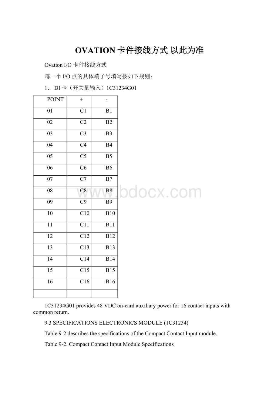
1.DI卡(开关量输入)1C31234G01
POINT
+
-
01
C1
B1
02
C2
B2
03
C3
B3
04
C4
B4
05
C5
B5
06
C6
B6
07
C7
B7
08
C8
B8
09
C9
B9
10
C10
B10
11
C11
B11
12
C12
B12
13
C13
B13
14
C14
B14
15
C15
B15
16
C16
B16
1C31234G01provides48VDCon-cardauxiliarypowerfor16contactinputswithcommonreturn.
9.3SPECIFICATIONSELECTRONICSMODULE(1C31234)
Table9-2describesthespecificationsoftheCompactContactInputmodule.
Table9-2.CompactContactInputModuleSpecifications
Description
Value
Numberofchannels
16
Onboardauxiliarypowersupply
42Vminimum55Vmaximum
Propagationdelay
7mSecmaximum
ContactbouncerejectionAlwaysrejectscontactchangeofstateAlwaysacceptscontactchangeofstate
<3mSec>7mSec
Closedcontactoutputcurrent
4mAminimum8mAmaximum
Diagnostics
InternalmoduleoperatingfaultsGroundFaultDetection
Dielectricisolation:
Channeltologic
1000VAC/DC
Modulepower
4.56Wtypical4.75Wmaximum
Operatingtemperaturerange
0to60qC(32qFto140qF)
9.4CompactContactInputTerminalBlockWiringInformation
Table9-2.CompactContactInputModuleSpecifications(Cont’d)
Description
Value
Storagetemperaturerange
-40qCto85qC(-40qFto185qF)
Humidity(non-condensing)
0to95%
9.4COMPACTCONTACTINPUTTERMINALBLOCKWIRINGINFORMATION
Theavailablefoaminserthasasimplifiedwiringdiagramlabelonitstop,whichappearsabovetheterminalblock.Thisdiagramindicateshowthewiringfromthefieldistobeconnectedtotheterminalblockinthebaseunit.ThediagramfortheCompactContactInputmoduleisillustratedinFigure9-1.Thefollowingtablelistsanddefinestheabbreviationsusedinthisdiagram.
Abbreviation
Definition
1+through16+
Contactinputpositiveterminalconnection
1-through16
Contactinputnegativeterminalconnection
Earthgroundterminals
PS+,PS-
AuxiliaryPowerSupplyterminals
RSV
Reservedterminal.Nointernalconnection
Figure9-1.TerminalBlockConnectionsfortheCompactContactInputModules
9.5CompactContactInputFieldWiringInformation
2.SOE卡(DI卡)1C31233G04
POINT
+
-
01
C1
B1
02
C2
B2
03
C3
B3
04
C4
B4
05
C5
B5
06
C6
B6
07
C7
B7
08
C8
B8
09
C9
B9
10
C10
B10
11
C11
B11
12
C12
B12
13
C13
B13
14
C14
B14
15
C15
B15
16
C16
B16
3.DO卡(带继电器开关量输出,250VAC)5A26457G01
POINT
NC
NO
C
01
1NC
1NO
1C
02
2NC
2NO
2C
03
3NC
3NO
3C
04
4NC
4NO
4C
05
5NC
5NO
5C
06
6NC
6NO
6C
07
7NC
7NO
7C
08
8NC
8NO
8C
09
9NC
9NO
9C
10
10NC
10NO
10C
11
11NC
11NO
11C
12
12NC
12NO
12C
13
13NC
13NO
13C
14
14NC
14NO
14C
15
15NC
15NO
15C
16
16NC
16NO
16C
5A26457G01containsaRelayOutputElectronicsmodulearelayoutputbaseassembly,and16FormCrelays(G2Rstyle).
Table20-3.RelayOutputBaseSpecifications(1C31223G01,G2RStyle)
Description
Value
Numberofrelays
16
RelayType
G2Relectromechanicalstylewith1FormCcontactstyle
Relaycontactratings
10amps@250VAC,PF=110amps@30VDC
Maximumpropagationtime
Operatetime:
15mSec,bounceapproximately=3mSecReleasetime:
10mSec,bounceapproximately=8mSec
Dielectricisolation:
Relaycontactstologic
2300VAC/DC
Relaybasepower
Auxiliarypower:
9.1Wtypical,11.68Wmaximum
Auxiliarypowersupply1
25Vtypical(beforeoutputauctioneeringdiodedropwithinOvationauxiliarypowersupply)25.5Vmaximum@60qC
Operatingtemperaturerange2
0to60qC(32qFto140qF)
20.4Specifications20.5RelayOutputTerminalBlockWiringInformation
Table20-3.RelayOutputBaseSpecifications(1C31223G01,G2RStyle)(Cont’d)
Description
Value
Storagetemperaturerange
-40to70qC(-40qFto158qF)
Humidity(non-condensing)
35-85%
1UseoftheinternalOvationauxiliarypowersupplyisrecommendedforrelayoutputmodules.2SeeadditionalapplicationderatinginformationcontainedinTable20-5.
Abbreviation
Definition
NC1
NormallyClosedcontactconnection
NO
NormallyOpencontactconnection
C
Commoncontactconnection
1DoNOTusetheNCterminalpositionwhenusingtheKUEPstylebaseassemblywithaFormXstylerelayinserted.Theterminalpositionshouldremainunconnected.
4,DO卡(带继电器开关量输出,150VDC)5A26458G02
POINT
NO
C
01
1NO
1C
02
2NO
2C
03
3NO
3C
04
4NO
4C
05
5NO
5C
06
6NO
6C
07
7NO
7C
08
8NO
8C
09
9NO
9C
10
10NO
10C
11
11NO
11C
12
12NO
12C
5A26458G02containsaRelayOutputElectronicsmodule,arelayoutputbaseassembly,and12FormXrelays(KUEPstyle).
Table20-4.RelayOutputBaseAssemblySpecifications(1C31222G01,KUEPStyle)
Description
Value
Numberofchannels
12
RelayType
KUEPelectromechanicalstyle:
5A26458G01Kit-1FormCcontacttype5A26458G02Kit-1FormXcontacttype5A26458G03Kit-Projectspecific
Relaycontactratings
FormCrelays:
10amps@240VAC,PF=0.83amps@150VDCFormXrelays:
10amps@240VAC,PF=0.810amps@150VDC
Typicalpropagationtime
Operatetime:
15mSec,excludingbounceReleasetime:
10mSec,excludingbounce
Dielectricisolation:
Relaycontactstologic
2200VAC/DC
Relaybasepower
Auxiliarypower:
23.45Wtypical,30.1Wmaximum(5A26458G01Kit-FormCrelays)15.9Wtypical,20.41Wmaximum(5A26458G02Kit-FormXrelays)
Auxiliarypowersupply1
25Vtypical(beforeoutputauctioneeringdiodedropwithinOvationauxiliarypowersupply)25.5Vmaximum@42qC(108qF)(FormCrelays)25.5Vmaximum@60qC(140qF)(FormXrelays)
Operatingtemperaturerange2
0to45qC(32qFto113qF)(5A26458G01Kit-FormCrelays)0to60qC(32qFto140qF)(5A26458G02Kit-FormXrelays)
Storagetemperaturerange
KUEPX:
-40to70qC(-40qFto158qF)KUEPC:
-40to50qC(-40qFto122qF)
1UseofinternalOvationauxiliarypowersupplyisrecommendedforRelayOutputmodules.2SeeadditionalapplicationderatinginformationcontainedinTable20-5.
6,DO卡(开关量输出,250VDC)1C31122G01/1C31125G02
POINT
NO
C
01
1RNO
1C
02
2RNO
2C
03
3RNO
3C
04
4RNO
4C
05
5RNO
5C
06
6RNO
6C
07
7RNO
7C
08
8RNO
8C
09
9RNO
9C
10
10RNO
10C
11
11RNO
11C
12
12RNO
12C
13
13RNO
13C
14
14RNO
14C
15
15RNO
15C
16
16RNO
16C
7,AI卡(4-20mA输入)1C31224G01/1C31227G01
DCS对现场供电(内供电)
注:
P(N)和CI(N),SH(N)和地(E)需短接
POINT
CI(n)
P(n)
+
-SH(n)
屏蔽E
1
A1
A2
B2
C2
C1
2
A3
A4
B4
C4
C3
3
A5
A6
B6
C6
C5
4
A7
A8
B8
C8
C7
5
A9
A10
B10
C10
C9
6
A11
A12
B12
C12
C11
7
A13
A14
B14
C14
C13
8
A15
A16
B16
C16
C15
内供电AI信号屏蔽线在DCS侧接地,现场侧悬空。
DCS不对现场供电(外供电)
POINT
+CI(n)
-A(n)
屏蔽
1
A1
B2
C2
2
A3
B4
C4
3
A5
B6
C6
4
A7
B8
C8
5
A9
B10
C10
6
A11
B12
C12
7
A13
B14
C14
8
A15
B16
C16
备注:
外供电的AI信号,分屏线接C2、C4……C16,分屏蔽线在现场端要接地。
8,AI卡(0-10VDC输入)5X00070G03/1C31227G02
在DCS侧接地
注:
-(N)和地(E)需短接
POINT
+
-
屏蔽
-(n)
1
A1
B2
C1
C2
2
A3
B4
C3
C4
3
A5
B6
C5
C6
4
A7
B8
C7
C8
5
A9
B10
C9
C10
6
A11
B12
C11
C12
7
A13
B14
C13
C14
8
A15
B16
C15
C16
在现场侧接地
POINT
+
-
屏蔽
1
A1
B2
A2
2
A3
B4
A4
3
A5
B6
A6
4
A7
B8
A8
5
A9
B10
A10
6
A11
B12
A12
7
A13
B14
A14
8
A15
B16
A16
9.AI卡HARTAnalogInputModule5X00058G01/5X00059G01
DCS对现场供电(内供电)
POINT
+
-
屏蔽
1
A1
B1
A2
2
A3
B3
A4
3
A5
B5
A6
4
A7
B7
A8
5
A9
B9
A10
6
A11
B11
A12
7
A13
B13
A14
8
A15
B15
A16
DCS不对现场供电(外供电)
POINT
+
-
屏蔽
1
B1
B2
A2
2
B3
B4
A4
3
B5
B6
A6
4
B7
B8
A8
5
B9
B10
A10
6
B11
B12
A12
7
B13
B14
A14
8
B15
B16
A16
10,RTD卡(热电阻)
8点每卡5X00119G01/5X00121G01
POINT
SRC
+
-
E(屏蔽线)
回线
1
B1
B2
C1
A1
C2
2
B3
B4
C3
A3
C4
3
B5
B6
C5
A5
C6
4
B7
B8
C7
A7
C8
5
B9
B10
C9
A9
C10
6
B11
B12
C11
A11
C12
7
B13
B14
C13
A13
C14
8
B15
B16
C15
A15
C16
注:
如为3线制接线方式,SRC与+短接,B1与B2,B3与B4………
4点每卡
POINT
+
-
屏蔽
回线
1
A2
A3
C1
A4
2
A6
A7
C5
A8
3
A10
A11
C9
A12
4
A14
A15
C13
A16
注:
如为3线制接线方式,SRC与+短接。
即A1与A2,A5与A6,A9与A10,A13与A14
11.TC卡(热电偶)5X00070G04/1C31116G04
POINT
+
-
屏蔽
1
A1
B2
A2
2
A3
B4
A4
3
A5
B6
A6
4
A7
B8
A8
5
A9
B10
A10
6
A11
B12
A12
7
A13
B14
A14
8
A15
B16
A16
12.AO卡(4-20mA输出)1C31129G03/1C31132G01
POINT
+
-
屏蔽
1
A2
B2
C1
2
A6
B6
C5
3
A10
B10
C9
4
A14
B14
C13
13.PI卡(脉冲输入)1C31147G01/1C31150G01
POINT
+
-
屏蔽
1
B4
A4
C17
2
B12
A12
C18
14.SpeedSensor卡(测速卡)1C31189G01/1C31192G01
+B15
-B16
15.ServoDriver卡(伺服卡)
侍服线圈接法:
SERVOVALVECOILBASEUNIT
STYLETERMINATIONBLOCK
CONNECTIONS
60OHM,60mAA5&B7
80OHM,40mAA6&B7
40OHM,40mAA7&B7
LVDT接法
输入级:
+16V---B3COM---C4
-16V---B4COM---A4
输出级:
MaximumDCLVDTBaseUnit
PositionFeedbackVoltageTerminationBlock
(OUT+-OUT-)Connections
7.4VdcB1&C1(HighRange)
16.LC卡(串口通讯卡)1C31166G01/1C31169G02
两线:
A15与B15、A16与B16、B14与B15短接。
信号线:
B15----接正端
B16----接负端
四线:
A14与A15、B14与B15短接
信号线:
A15----接接收正端
A16----接接收负端
B15----接发送正端
B16----接发送负端
屏蔽线都是系统侧接地则接C17、系统外接地则接C16。
 升级会员
升级会员 