VerificationExample.docx
《VerificationExample.docx》由会员分享,可在线阅读,更多相关《VerificationExample.docx(11页珍藏版)》请在冰豆网上搜索。
VerificationExample
|VerificationExample||Preprocessing||Solution||Postprocessing||CommandLine|
|BicycleExample||Preprocessing||Solution||Postprocessing||CommandLine|
Introduction
ThistutorialwascreatedusingANSYS7.0tosolveasimple3Dspaceframeproblem.
ProblemDescription
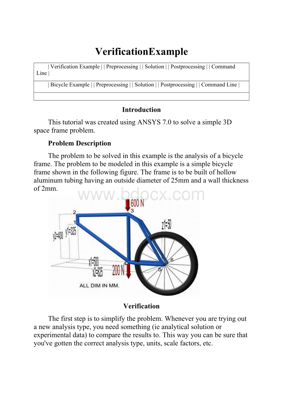
Theproblemtobesolvedinthisexampleistheanalysisofabicycleframe.Theproblemtobemodeledinthisexampleisasimplebicycleframeshowninthefollowingfigure.Theframeistobebuiltofhollowaluminumtubinghavinganoutsidediameterof25mmandawallthicknessof2mm.
Verification
Thefirststepistosimplifytheproblem.Wheneveryouaretryingoutanewanalysistype,youneedsomething(ieanalyticalsolutionorexperimentaldata)tocomparetheresultsto.Thiswayyoucanbesurethatyou'vegottenthecorrectanalysistype,units,scalefactors,etc.
Thesimplifiedversionthatwillbeusedforthisproblemisthatofacantileverbeamshowninthefollowingfigure:
Preprocessing:
DefiningtheProblem
1.GivetheSimplifiedVersionaTitle(suchas'VerificationModel').
UtilityMenu>File>ChangeTitle
2.EnterKeypoints
Forthissimpleexample,thesekeypointsaretheendsofthebeam.
oWearegoingtodefine2keypointsforthesimplifiedstructureasgiveninthefollowingtable
keypoint
coordinate
x
y
z
1
0
0
0
2
500
0
0
oFromthe'ANSYSMainMenu'select:
Preprocessor>Modeling>Create>Keypoints>InActiveCS
3.FormLines
Thetwokeypointsmustnowbeconnectedtoformabarusingastraightline.
oSelect:
Preprocessor>Modeling>Create>Lines>Lines>StraightLine.
oPickkeypoint#1(i.e.clickonit).Itwillnowbemarkedbyasmallyellowbox.
oNowpickkeypoint#2.Apermanentlinewillappear.
oWhenyou'redone,clickon'OK'inthe'CreateStraightLine'window.
4.DefinetheTypeofElement
Itisnownecessarytocreateelementsonthisline.
oFromthePreprocessorMenu,select:
ElementType>Add/Edit/Delete.
oClickonthe'Add...'button.Thefollowingwindowwillappear:
oForthisexample,wewillusethe3Delasticstraightpipeelementasselectedintheabovefigure.Selecttheelementshownandclick'OK'.Youshouldsee'Type1PIPE16'inthe'ElementTypes'window.
oClickonthe'Options...'buttoninthe'ElementTypes'dialogbox.Thefollowingwindowwillappear:
oClickandholdtheK6button(secondfromthebottom),andselect'IncludeOutput'andclick'OK'.Thisgivesusextraforceandmomentoutput.
oClickon'Close'inthe'ElementTypes'dialogboxandclosethe'ElementType'menu.
5.DefineGeometricProperties
Wenowneedtospecifygeometricpropertiesforourelements:
oInthePreprocessormenu,selectRealConstants>Add/Edit/Delete
oClickAdd...andselect'Type1PIPE16'(actuallyitisalreadyselected).Clickon'OK'.
oEnterthefollowinggeometricproperties:
oOutsidediameterOD:
25
oWallthicknessTKWALL:
2
Thisdefinesanoutsidepipediameterof25mmandawallthicknessof2mm.
oClickon'OK'.
o'Set1'nowappearsinthedialogbox.Clickon'Close'inthe'RealConstants'window.
6.ElementMaterialProperties
Youthenneedtospecifymaterialproperties:
oInthe'Preprocessor'menuselectMaterialProps>MaterialModels...
oDoubleclickStructural>Linear>Elasticandselect'Isotropic'(doubleclickonit)
oClosethe'DefineMaterialModelBehavior'Window.
WearegoingtogivethepropertiesofAluminum.Enterthefollowingfield:
EX70000
PRXY0.33
oSetthesepropertiesandclickon'OK'.
7.MeshSize
oInthePreprocessormenuselectMeshing>SizeCntrls>ManualSize>Lines>AllLines
oInthesize'SIZE'field,enterthedesiredelementlength.Forthisexamplewewantanelementlengthof2cm,therefore,enter'20'(i.e20mm)andthenclick'OK'.Notethatwehavenotyetmeshedthegeometry,wehavesimplydefinedtheelementsizes.
(Alternatively,wecouldenterthenumberofdivisionswewantintheline.Foranelementlengthof2cm,wewouldenter25[ie25divisions]).
8.NOTE
Itisnotnecessarytomeshbeamelementstoobtainthecorrectsolution.However,meshingisdoneinthiscasesothatwecanobtainresults(iestress,displacement)atintermediatepositionsonthebeam.
9.Mesh
Nowtheframecanbemeshed.
oInthe'Preprocessor'menuselectMeshing>Mesh>Linesandclick'PickAll'inthe'MeshLines'Window
10.SavingYourWork
UtilityMenu>File>Saveas....Selectthenameandlocationwhereyouwanttosaveyourfile.
SolutionPhase:
AssigningLoadsandSolving
1.DefineAnalysisType
oFromtheSolutionMenu,select'AnalysisType>NewAnalysis'.
oEnsurethat'Static'isselectedandclick'OK'.
2.ApplyConstraints
oIntheSolutionmenu,selectDefineLoads>Apply>Structural>Displacement>OnKeypoints
oSelecttheleftendoftherod(Keypoint1)byclickingonitintheGraphicsWindowandclickon'OK'inthe'ApplyU,ROTonKPs'window.
oThislocationisfixedwhichmeansthatalltranslationalandrotationaldegreesoffreedom(DOFs)areconstrained.Therefore,select'AllDOF'byclickingonitandenter'0'intheValuefieldandclick'OK'.
3.ApplyLoads
Asshowninthediagram,thereisaverticallydownwardloadof100Nattheendofthebar
oIntheStructuralmenu,selectForce/Moment>onKeypoints.
oSelectthesecondKeypoint(rightendofbar)andclick'OK'inthe'ApplyF/M'window.
oClickonthe'Directionofforce/mom'atthetopandselectFY.
oEnteravalueof-100inthe'Force/momentvalue'boxandclick'OK'.
oTheforcewillappearinthegraphicswindowasaredarrow.
Theappliedloadsandconstraintsshouldnowappearasshownbelow.
4.SolvingtheSystem
WenowtellANSYStofindthesolution:
oSolution>Solve>CurrentLS
Postprocessing:
ViewingtheResults
1.HandCalculations
Now,sincethepurposeofthisexercisewastoverifytheresults-weneedtocalculatewhatweshouldfind.
Deflection:
Themaximumdeflectionoccursattheendoftherodandwasfoundtobe6.2mmasshownabove.
Stress:
Themaximumstressoccursatthebaseoftherodandwasfoundtobe64.9MPaasshownabove(purebendingstress).
2.ResultsUsingANSYS
Deformation
ofromtheMainMenuselectGeneralPostprocfromthe'ANSYSMainMenu'.Inthismenuyouwillfindavarietyofoptions,thetwowhichwewilldealwithnoware'PlotResults'and'ListResults'
oSelectPlotResults>DeformedShape.
oSelect'Def+undefedge'andclick'OK'toviewboththedeformedandtheundeformedobject.
oObservethevalueofthemaximumdeflectionintheupperlefthandcorner(shownheresurroundedbyablueborderforemphasis).Thisisidenticaltothatobtainedviahandcalculations.
Deflection
Foramoredetailedversionofthedeflectionofthebeam,
oFromthe'GeneralPostproc'menuselectPlotresults>ContourPlot>NodalSolution.
oSelect'DOFsolution'and'USUM'.Leavetheotherselectionsasthedefaultvalues.Click'OK'.
oYoumaywanttohaveamoreusefulscale,whichcanbeaccomplishedbygoingtotheUtilityMenuandselectingPlotControls>Style>Contours>UniformContours
oThedeflectioncanalsobeobtainedasalistasshownbelow.GeneralPostproc>ListResults>NodalSolution...select'DOFSolution'and'ALLDOFs'fromthelistsinthe'ListNodalSolution'windowandclick'OK'.Thismeansthatwewanttoseealistingofalltranslationalandrotationaldegreesoffreedomfromthesolution.Ifwehadonlywantedtoseethedisplacementsforexample,wewouldhavechosen'ALLUs'insteadof'ALLDOFs'.
oAretheseresultswhatyouexpected?
Again,themaximumdeflectionoccursatnode2,therightendoftherod.Alsonotethatalltherotationalandtranslationaldegreesoffreedomwereconstrainedtozeroatnode1.
oIfyouwantedtosavetheseresultstoafile,usethemousetogotothe'File'menu(attheupperleft-handcornerofthislistwindow)andselect'Saveas'.
Stresses
Forlineelements(iebeams,spars,andpipes)youwillneedtousetheElementTabletogainaccesstoderiveddata(iestresses,strains).
oFromtheGeneralPostprocessormenuselectElementTable>DefineTable...
oClickon'Add...'
 升级会员
升级会员 