稳态热分析案例ANSYS 150版.docx
《稳态热分析案例ANSYS 150版.docx》由会员分享,可在线阅读,更多相关《稳态热分析案例ANSYS 150版.docx(14页珍藏版)》请在冰豆网上搜索。
稳态热分析案例ANSYS150版
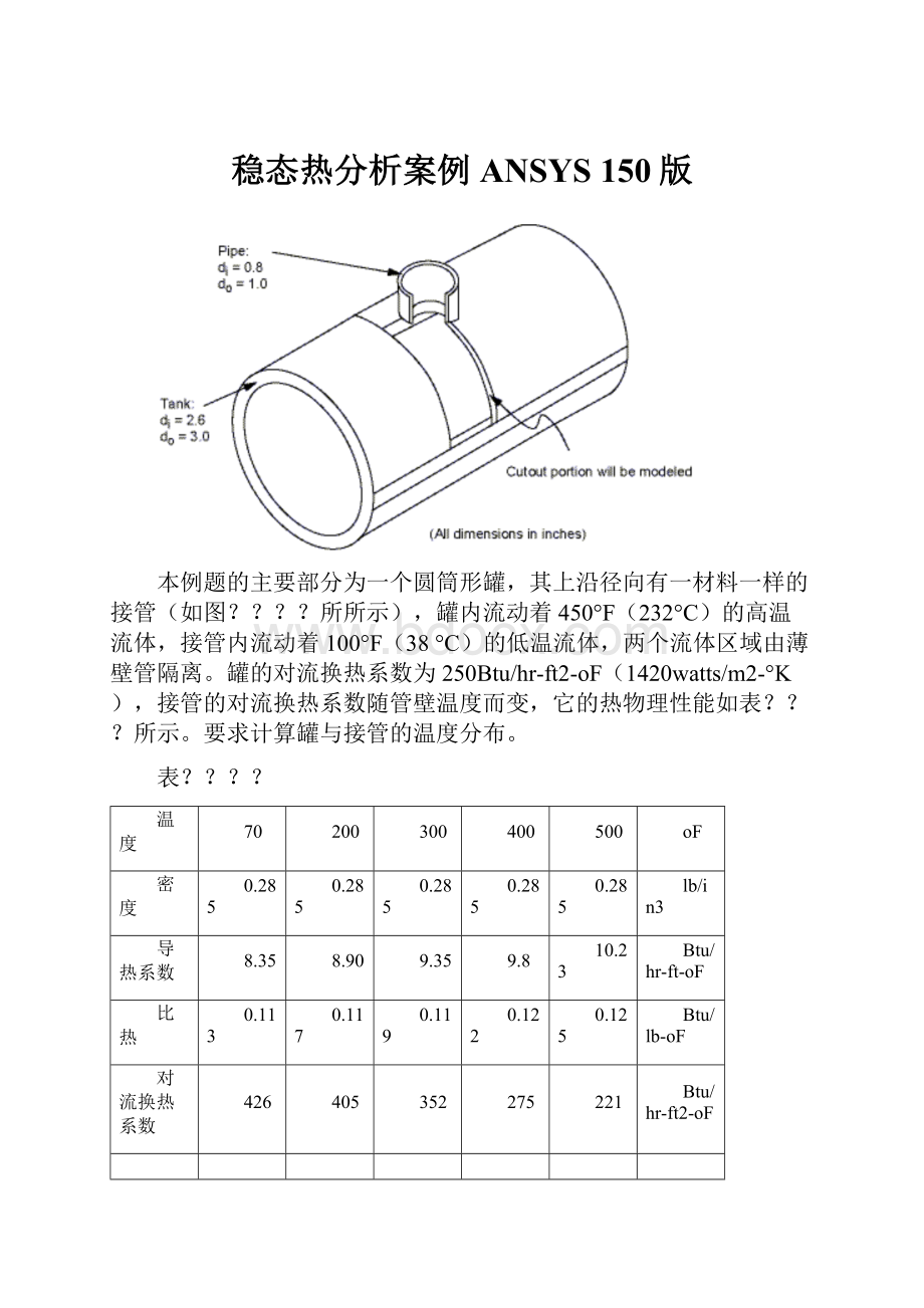
本例题的主要部分为一个圆筒形罐,其上沿径向有一材料一样的接管(如图?
?
?
?
所所示),罐内流动着450°F(232°C)的高温流体,接管内流动着100°F(38°C)的低温流体,两个流体区域由薄壁管隔离。
罐的对流换热系数为250Btu/hr-ft2-oF(1420watts/m2-°K),接管的对流换热系数随管壁温度而变,它的热物理性能如表?
?
?
所示。
要求计算罐与接管的温度分布。
表?
?
?
?
温度
70
200
300
400
500
oF
密度
0.285
0.285
0.285
0.285
0.285
lb/in3
导热系数
8.35
8.90
9.35
9.8
10.23
Btu/hr-ft-oF
比热
0.113
0.117
0.119
0.122
0.125
Btu/lb-oF
对流换热系数
426
405
352
275
221
Btu/hr-ft2-oF
6.5.1预处理
Step1:
确定分析标题
起动ANSYS后,开始一个分析,需要输入一个标题,按下面方法进行操作:
1.选择Utility Menu>File>ChangeTitle,弹出相应对话框
2.输入 Steady-statethermalanalysisofpipejunction。
3.点击OK。
Step2:
设置分析单位系统
Youneedtospecifyunitsofmeasurementfortheanalysis.Forthispipejunctionexample,measurementsusetheU.S.Customarysystemofunits(basedoninches).Tospecifythis,typethecommand /UNITS,BINintheANSYSInputwindowandpressENTER.在分析之前,需要为分析系统设定单位系统,
Step3:
DefinetheElementType
Theexampleanalysisusesathermalsolidelement.Todefineit,dothefollowing:
1.Choose Main Menu>Preprocessor>ElementType>Add/Edit/Delete.TheElementTypesdialogboxappears.
2.ClickonAdd.TheLibraryofElementTypesdialogboxappears.
3.Inthelistontheleft,scrolldownandpick(highlight)"ThermalSolid."Inthelistontheright,pick"Brick20node90."
4.ClickonOK.
5.ClickonClosetoclosetheElementTypesdialogbox.
Step4:
DefineMaterialProperties
Todefinematerialpropertiesfortheanalysis,performthesesteps:
1.Choose Main Menu>Preprocessor>MaterialProps>MaterialModels.TheDefineMaterialModelBehaviordialogboxappears.
2.IntheMaterialModelsAvailablewindow,double-clickonthefollowingoptions:
Thermal,Density.Adialogboxappears.
3.Enter.285forDENS(Density),andclickonOK.MaterialModelNumber1appearsintheMaterialModelsDefinedwindowontheleft.
4.IntheMaterialModelsAvailablewindow,double-clickonthefollowingoptions:
Conductivity,Isotropic.Adialogboxappears.
5.ClickontheAddTemperaturebuttonfourtimes.Fourcolumnsareadded.
6.IntheT1throughT5fields,enterthefollowingtemperaturevalues:
70,200,300,400,and500.Selecttherowoftemperaturesbydraggingthecursoracrossthetextfields.ThencopythetemperaturesbypressingCtrl-c.
7.IntheKXX(ThermalConductivity)fields,enterthefollowingvalues,inorder,foreachofthetemperatures,thenclickonOK.Notethattokeeptheunitsconsistent,eachofthegivenvaluesofKXXmustbedividedby12.YoucanjustinputthefractionsandhaveANSYSperformthecalculations.
8.35/12
8.90/12
9.35/12
9.80/12
10.23/12
8.IntheMaterialModelsAvailablewindow,double-clickonSpecificHeat.Adialogboxappears.
9.ClickontheAddTemperaturebuttonfourtimes.Fourcolumnsareadded.
10.WiththecursorpositionedintheT1field,pastethefivetemperaturesbypressingCtrl-v.
11.IntheC(SpecificHeat)fields,enterthefollowingvalues,inorder,foreachofthetemperatures,thenclickonOK.
.113
.117
.119
.122
.125
12.Choosemenupath Material>NewModel,thenenter2forthenewMaterialID.ClickonOK.MaterialModelNumber2appearsintheMaterialModelsDefinedwindowontheleft.
13.IntheMaterialModelsAvailablewindow,double-clickonConvectionorFilmCoef.Adialogboxappears.
14.ClickontheAddTemperaturebuttonfourtimes.Fourcolumnsareadded.
15.WiththecursorpositionedintheT1field,pastethefivetemperaturesbypressingCtrl-v.
16.IntheHF(FilmCoefficient)fields,enterthefollowingvalues,inorder,foreachofthetemperatures.Tokeeptheunitsconsistent,eachvalueofHFmustbedividedby144.Asinstep7,youcaninputthedataasfractionsandletANSYSperformthecalculations.
426/144
405/144
352/144
275/144
221/144
17.ClickontheGraphbuttontoviewagraphofFilmCoefficientsvs.temperature,thenclickonOK.
18.Choosemenupath Material>Exit toremovetheDefineMaterialModelBehaviordialogbox.
19.ClickonSAVE_DBontheANSYSToolbar.
Step5:
DefineParametersforModeling
1.Choose Utility Menu>Parameters>ScalarParameters.TheScalarParameterswindowappears.
2.Inthewindow'sSelectionfield,enterthevaluesshownbelow.(Donotenterthetextinparentheses.)PressENTERaftertypingineachvalue.Ifyoumakeamistake,simplyretypethelinecontainingtheerror.
RI1=1.3(Insideradiusofthecylindricaltank)
RO1=1.5(Outsideradiusofthetank)
Z1=2(Lengthofthetank)
RI2=.4(Insideradiusofthepipe)
RO2=.5(Outsideradiusofthepipe)
Z2=2(Lengthofthepipe)
3.ClickonClosetoclosethewindow.
Step6:
CreatetheTankandPipeGeometry
1.Choose Main Menu>Preprocessor>Modeling>Create>Volumes>Cylinder>ByDimensions.TheCreateCylinderbyDimensionsdialogboxappears.
2.Setthe"Outerradius"fieldto RO1,the"Optionalinnerradius"fieldto RI1,the"Zcoordinates"fieldsto 0 and Z1 respectively,andthe"Endingangle"fieldto 90.
3.ClickonOK.
4.Choose Utility Menu>WorkPlane>OffsetWPbyIncrements.TheOffsetWPdialogboxappears.
5.Setthe"XY,YZ,ZXAngles"fieldto 0,-90.
6.ClickonOK.
7.Choose Main Menu>Preprocessor>Modeling>Create>Volumes>Cylinder>ByDimensions.TheCreateCylinderbyDimensionsdialogboxappears.
8.Setthe"Outerradius"fieldto RO2,the"Optionalinnerradius"fieldto RI2,the"Zcoordinates"fieldsto 0 and Z2 respectively.Setthe"Startingangle"fieldto -90and the"EndingAngle"to0.
9.ClickonOK.
10.Choose Utility Menu>WorkPlane>AlignWPwith>GlobalCartesian.
Step7:
OverlaptheCylinders
1.Choose Main Menu>Preprocessor>Modeling>Operate>Booleans>Overlap>Volumes.TheOverlapVolumespickingmenuappears.
2.ClickonPickAll.
Step8:
ReviewtheResultingModel
Beforeyoucontinuewiththeanalysis,quicklyreviewyourmodel.Todoso,followthesesteps:
1.Choose Utility Menu>PlotCtrls>Numbering.ThePlotNumberingControlsdialogboxappears.
2.ClicktheVolumenumbersradiobuttontoOn,thenclickonOK.
3.Choose Utility Menu>PlotCtrls>ViewSettings>ViewingDirection.Adialogboxappears.
4.Setthe"Coordsofviewpoint"fieldsto(-3,-1,1),thenclickonOK.
5.Reviewtheresultingmodel.
6.ClickonSAVE_DBontheANSYSToolbar.
Step9:
TrimOffExcessVolumes
Inthisstep,deletetheoverlappingedgesofthetankandthelowerportionofthepipe.
1.Choose Main Menu>Preprocessor>Modeling>Delete>VolumeandBelow.TheDeleteVolumeandBelowpickingmenuappears.
2.Inthepickingmenu,type3,4andpresstheENTERkey.ThenclickonOKintheDeleteVolumeandBelowpickingmenu.
Step10:
CreateComponentAREMOTE
Inthisstep,youselecttheareasattheremoteYandZedgesofthetankandsavethemasacomponentcalledAREMOTE.Todoso,performthesetasks:
1.Choose Utility Menu>Select>Entities.TheSelectEntitiesdialogboxappears.
2.Inthetopdropdownmenu,selectAreas.Intheseconddropdownmenu,selectByLocation.ClickontheZCoordinatesradiobutton.
3.Setthe"Min,Max"fieldto Z1.
4.ClickonApply.
5.ClickontheYCoordinatesandAlsoSeleradiobuttons.
6.Setthe"Min,Max"fieldto 0.
7.ClickonOK.
8.Choose Utility Menu>Select>Comp/Assembly>CreateComponent.TheCreateComponentdialogboxappears.
9.Setthe"Componentname"fieldto AREMOTE. Inthe"Componentismadeof"menu,selectAreas.
10.ClickonOK.
Step11:
OverlayLinesonTopofAreas
Dothefollowing:
1.Choose Utility Menu>PlotCtrls>Numbering.ThePlotNumberingControlsdialogboxappears.
2.ClicktheAreaandLinenumberradioboxestoOnandclickonOK.
3.Choose Utility Menu>Plot>Areas.
4.Choose Utility Menu>PlotCtrls>EraseOptions.
5.Set"ErasebetweenPlots"radiobuttontoOff.
6.Choose Utility Menu>Plot>Lines.
7.Choose Utility Menu>PlotCtrls>EraseOptions.
8.Set"ErasebetweenPlots"radiobuttontoOn.
Step12:
ConcatenateAreasandLines
Inthisstep,youconcatenateareasandlinesattheremoteedgesofthetankformappedmeshing.Todoso,followthesesteps:
1.Choose Main Menu>Preprocessor>Meshing>Mesh>Volumes>Mapped>Concatenate>Areas.TheConcatenateAreaspickingmenuappears.
2.ClickonPickAll.
3.Choose Main Menu>Preprocessor>Meshing>Mesh>Volumes>Mapped>Concatenate>Lines.Apickingmenuappears.
4.Pick(clickon)lines12and7(orenterinthepicker).
5.ClickonApply.
6.Picklines10and5(orenterinpicker).
7.ClickonOK.
Step13:
SetMeshingDensityAlongLines
1.Choose Main Menu>Preprocessor>Meshing>SizeCntrls>ManualSize>Lines>PickedLines.TheElementSizeonPickedLinespickingmenuappears.
2.Picklines6and20(orenterinthepicker).
3.ClickonOK.TheElementSizesonPickedLinesdialogboxappears.
4.Setthe"No.ofelementdivisions"fieldto4.
5.ClickonOK.
6.Choose Main Menu>Preprocessor>Meshing>SizeCntrls>ManualSize>Lines>PickedLines.Apickingmenuappears.
7.Pickline40(orenterinthepicker).
8.ClickonOK.TheElementSizesonPickedLinesdialogboxappears.
9.Setthe"No.ofelementdivisions"fieldto6.
10.ClickonOK.
Step14:
MeshtheModel
Inthissequenceofsteps,yousettheglobalelementsize,setmappedmeshing,thenmeshthevolumes.
1.Choose Utility Menu>Select>Everything.
2.Choose Main Menu>Preprocessor>Meshing>SizeCntrls>ManualSize>Global>Size.TheGlobalElementSizesdialogboxappears.
3.Setthe"Elementedgelength"fieldto0.4andclickonOK.
4.Choose Main Menu>Preprocessor>Meshing>MesherOpts.TheMesherOptionsdialogboxappears.
5.SettheMesherTyperadiobuttontoMappedandclickonOK.TheSetElementShapedialogboxappears.
6.Inthe2-Dshapekeydropdownmenu,selectQuadandclickonOK.
7.ClickontheSAVE_DBbuttonontheT
 升级会员
升级会员 