AnalogTestWord下载.docx
《AnalogTestWord下载.docx》由会员分享,可在线阅读,更多相关《AnalogTestWord下载.docx(15页珍藏版)》请在冰豆网上搜索。
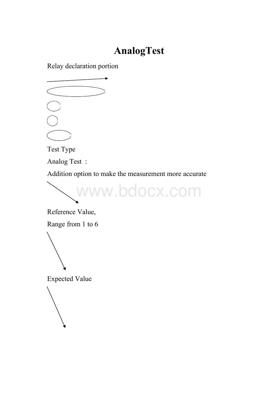
AnalogTest:
Hardwareneeded:
a.Voltagesource
b.Previsionreferenceresistor
c.MOA
d.Internalvoltmeter
e.Relayforconnection
s-bus
i-bus
IRx
IRef
Gain=Vmoa/Vs
IRx=IRef;
wheresummingNode=0voltwithhighinputimpedanceofop-amp
Vs/Rx=Vmoa/Rref=0volt
Vs/Rx=-Vmoa/Rref
Rx=-(Vs/Vmoa)Rref
Gain=-Rref/Rx
Tomakeagoodmeasurement,Galwaysneedtobebetween–1to–10.Closerto–1,thebestandstabletestwillbe.
WhatNeedToDoIfRmeasure<
Rxactual
Question:
WhatcancausevoltagedroponRxis<
actual?
?
Answer:
Rxisfix,wheretheonlyvariableiscurrentflowthruRx,IRx
Example:
IfthereisanotherpathwhichisconnecttoRx,IRx<
IRef,whereIRef=IRx+Ip
Solution:
GroundingtheZsgandZig,willpreventcurrentflowonthatpath.
Therefore,thecurrentflowthruRxwillresumeas:
IRxΞIRef;
whereIp=0amp
WhatYouNeedToDoIfRmeasure>
WhatcancausevoltagedroponRxbiggerthenexpected?
Additionimpedancefroms-busortheinternalvoltagesourcefromASRUcard,wheretheRx=Rx+Z
IRef=Vmoa/Rref,
However…………
IRx<
>
Vs/Rx,but
IRx=Vs/(Rx+Rs+Ri)
SolutiononadditionimpedanceformS-bus,Zs:
∙PlaceaDVMtosensethevoltagedroponZsbyadding“a-bus”
∙TheinputimpedanceofDVMisprettyhighandnocurrentwillthanflowthru.ThiswillnotreducethecurrentflowthurRx.
SolutiononadditionimpedancefromI-bus,Zi:
Addb-bustomovethevirtualgroundclosetoDUT
Add“en”option,toenhance
a.VoltagemeasurementacrossRRef
b.ActualmeasurementonVsinsteadofassumeduringmeasurementcalculation
WhathappenifthereisG-BusImpedance:
WithG-Businternalimpedance,itmaycauseIRx<
IRef.
Rxmeasure>
Rxactual
AdditionlbustothecircuitrywillhelptoreduceG-busimpedance.
Note:
TheMOAimpedanceisinfinite,andnocurrentwillthenflowthruL-bus
path.
Thereis2waysofwritingthel-busconnection:
a.connectgto“node#”;
lto“node#”
b.connectglto“node#”
CompleteExamplewithallOption:
AnalogOption:
a.reX
∙referenceresistorforMOA
∙range:
re1tore6:
re1=10ohm;
101
re2=100ohm;
102
∙usetodefineamostaccurateGforanalogmeasurement
c.arX
∙specifyrangesettingforASRU’sinternalmultimeter,MOA
∙arXusetosetcorrectexpectedoutputvoltage
∙userseldonchangeonthissetting
∙default:
100mVforanalogmeasurement
d.amX
∙Vs,sourcevoltagerangesetting
∙Rangeof–10Vto+10V
∙Defaultvalue,Vs=100mV
∙Withrefertospec,measurepassivecomponentbyusingsourceof100mV
e.wb
∙bandwidthofMOA
∙useduringhihgMOAgainisneededathighfrequencytest
∙wbnormallynotuseduringre1&
re2setting,oritwillintenttosendMOAtosaturationstatus
f.waitX
∙delaystatement
∙itwillwaittoexecuteeachtimevoltagesourceischanges
∙rangefrom0to9.99999sec
∙normalcaseusingmsec
g.icoX
∙currentcomplianceofsource
∙ico0:
35mA
∙ico1:
150mA
∙bydefault35mA
h.frX
∙frequencyofsource,Vs
∙Usingduringcapacitor&
inductormeasurement,accomponentmeasurement
∙3ranges:
128,1024&
8192
∙iffrXisused,thesourcewillautomaticallychangefromDCtoAC
i.comp/nocomp
∙forcapacitorlearningpurpose
∙comp:
willrequestalearnstatementtothecapacitor,normallyuseon<
200pF
∙nocomp:
indicatethecapacitorwillnotperformlearningsection.
∙Learncapacitorwillalwaysdoduringthe1strunofthetest
j.Ed
∙Forlinenoiserejection
∙Usetogetherwithfr128
∙Thisstatementwillincreasetesttimeofabout17.5msecto20msec
k.En
Enhanceoption
Thisresultamultiplemeasurementondevice
With“en”,Vs,Vmoa,VrefandVitoMOAwillmeasure
Itwillincuradditiontesttime
l.sa
sensebustoreduceimpedanceofs-bustoRxmeasurement
m.sb
sensebustomovethevirtualgroundreferencetoavoidimpactfromimpedanceofI-bustoRx
n.sl
sensebustoreduceimpactfromg-busimpedancetoRxmeasurement
CapacitorTestingHint:
Someteststructureusingasresistor,capacitorisusingMOAconceptwithACsourceinsteadofDC.
Therewillbeneededforcapacitortohaveacompensationstatementduetosomecapacitorinducebetweentesterandfixturewillcausesomemis-readingonthemeasurement.
Thecompensationstatementwillbeuseonthecapacitorwhich<
100pF(Sometimetobesafe,470pFwillexecuteundercompoption)
RecommendedCapacitorMeasurementOption:
Diode&
ZenerDiodeTestConfiguration:
Zenerwillusethesameconfiguration,whereforwardbiasvoltagemeasurementfordiodeandreversebiasvoltageforzener.
Diode:
0.7volt(700mvolt):
forwardbiasvoltage
Zener:
18volt:
reversebiasvoltage
LED:
2.5volt:
HinttoTestDiode&
a.Diode:
Setvoltagecompliance(co)valueatealst1voltgreaterthanhihgtestlimit
Useguardingtoeliminatetheeffectogimpedanceinparallelwithdiodeundertest
EnsureMOAoutputdoesnotexceed15Vdcor14Vpk
b.Zener:
Setvoltagecompliance,coto10volt,and8.99voltsforauxiliarysource.
aroptionforzenerwillbewithinrangeof0to18volt
Donotuseguardingonzenertest
FETTestConfiguration:
TheFETtest,nfetrandpfetr,measureontheresistor(Ron)ofN-channelandP-channelFETsresepctively.
Thes-bus(sourcebus)andI-bus(detectorbus)areconnectedtothesourceanddrainoftheFET.
Theguard,G-busisconnectedtothegateoftheFET.
N-channelFETsaretestedwithapositivesource
P-ChannelFETsaretestedwithanegativesource
HintForFETstest:
BelowshowntherecommendedReferenceElement(re)RangeofRontest
froption,ACsourcecanbeusetoreducetheeffectofparallelimpedance
 升级会员
升级会员 