北美压铸压铸件公差标准NADCA Standard BriefWord格式文档下载.docx
《北美压铸压铸件公差标准NADCA Standard BriefWord格式文档下载.docx》由会员分享,可在线阅读,更多相关《北美压铸压铸件公差标准NADCA Standard BriefWord格式文档下载.docx(9页珍藏版)》请在冰豆网上搜索。
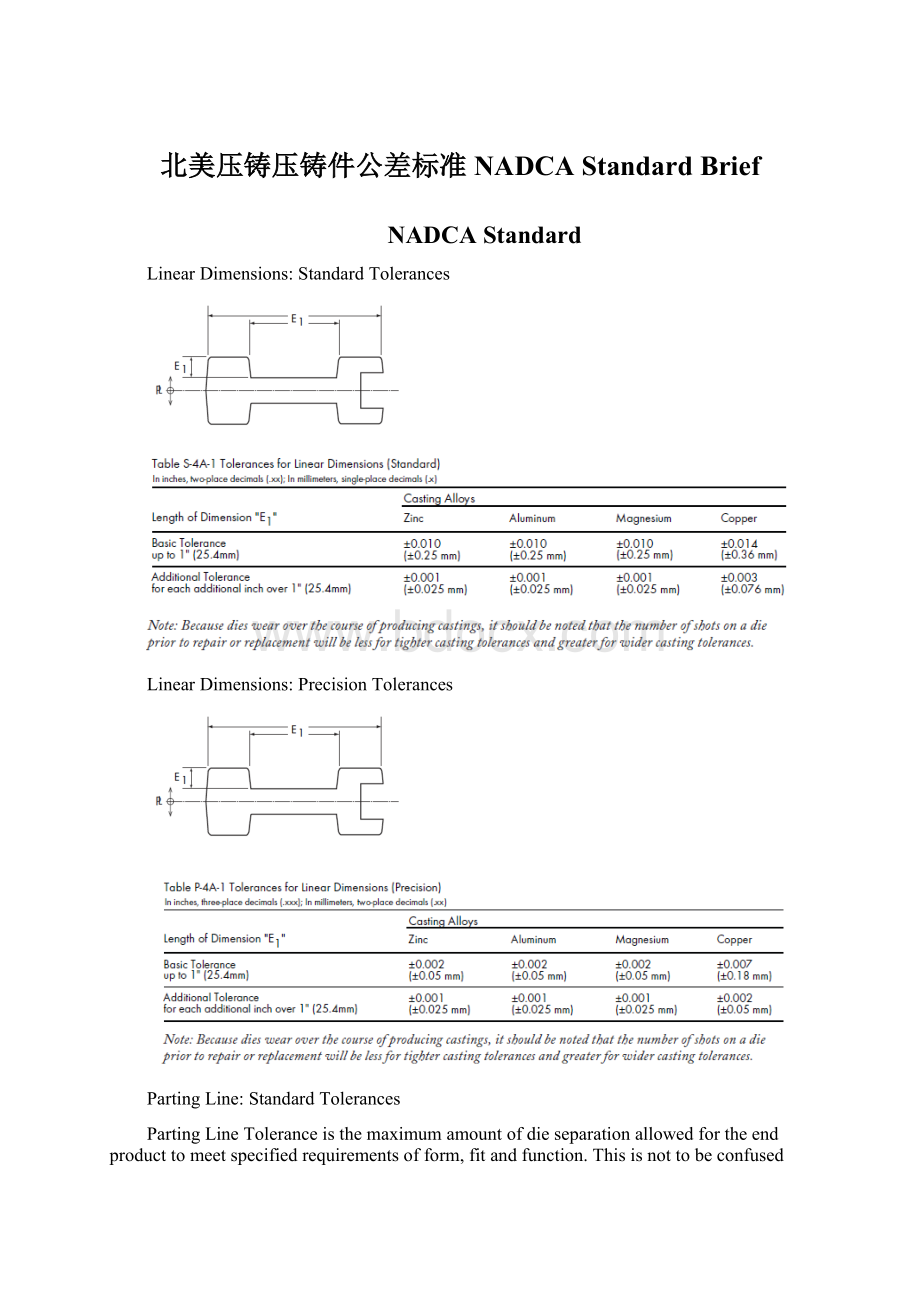
Thetotalpartthicknessincludingbothdiehalvesis5.00in.(127mm)whichismeasuredperpendiculartothepartingdieplane(dimension“E2E1”).FromtableS-4A-1,theLinearToleranceis±
0.010forthefirstinchand±
0.001foreachofthefouradditionalinches.TheLinearToleranceof±
0.014inchesiscombinedwiththeProjectedAreaToleranceof+0.012toyieldaStandardPartingLineToleranceof+0.026/-0.014in.orinmetricterms±
0.35mmfromLinearTolerancetableS-4A-1plus+0.30mmfromProjectedAreaTolerancetableS-4A-2=+0.65/-0.35mm.
PartingLineShift:
StandardTolerance
PartingLineShiftTolerance
Thecavityareaatthepartinglineis75inchessquared.FromTableS-4A-6,theProjectedAreaPartingLineShiftToleranceis±
0.006(±
0,152mm).ThisisaddedtotheLinearTolerancefromtableS/P-4A-1.
DraftRequirements:
Inthecaseofaninsidesurfaceforanaluminumcastpart,forwhichtheconstant“C”is30(6mm),therecommendedStandardDraftatthreedepthsis:
CoredHolesforCutThreads:
Coredholesforcutthreadsarecastholesthatrequirethreadstobecut(tapped)intothemetal.Thetablebelowprovidesthedimensionaltolerancesfordiameter,depthanddraftforeachspecifiedthreadtype(UnifiedandMetricSeries).Whenrequired,coredholesinAl,Mg,ZnandZAmaybetappedwithoutremovingdraft.ThisStandardTolerancerecommendationisbasedonallowing85%offullthreaddepthatthebottomD2(smallend)ofthecoredholeand55%atthetopD1(largeend)ofthecoredhole.Acountersinkorradiusisalsorecommendedatthetopofthecoredhole.Thisprovidesreliefforanydisplacedmaterialandcanalsoservetostrengthenthecore.
ThreadsextendthroughthecoredholeasbyY.Xshowstheactualholedepth.Aswiththecountersinkatthetopofthehole,theextraholelengthprovidesrelieffordisplacedmaterialandallowsforfullthreadengagement.Tolerancesbelowapplytoallalloys.
TableS-4A-9:
CoredHolesforCutThreads(StandardTolerances)–UnifiedSeriesandMetricSeries
AdditionalConsiderationsforLargeCastings
1FilletRadii:
1.1:
Definition:
Wallthicknessisthedistancebetweentwoparallelornearlyparallelsurfaces.Wallthicknessmayvarydependingontheapplicationofdraft.Wallthicknessshouldbemaintainedasuniformaspossible.Ageneralguidelinewouldbetokeeptherangeofthicknesswithin2Xofthethinnestwall.Asecondguidelineistokeepthewallasthinaspossibletomeetthecastingsfunctionalrequirements.
1.2:
General:
0.14”(3.5mm(+/-0.5mm)1.2.1Deviations:
fromthenominalconditionarebaseduponproductfunctionandmanufacturingprocessrequirements.
2Radii:
2.1FilletRadii:
2.1.1General:
0.14”(+0.08/-0.04”)[3.5mm(+2.0mm/-1.0mm)]
2.1.1.1Deviations:
2.1.2Minimum:
0.060”(1.5mm)
2.2CornerRadii:
2.2.1General:
0.060”(+0.08/-0.04”)[1.5mm(+2mm/-1mm)]
2.2.1.1Deviations:
2.2.2Minimum:
0.020”(0.5mm)
3Cores:
3.1Guidelines:
Coresshouldbeusedtominimizemachiningstock,andshouldbepulledperpendiculartoeachother.Usesteppedcoreswherepossibletominimizefinishstock,reduceheavysections,andminimizeporosity.
3.2Minimum:
Coredholediametertobe0.25”(6.0mm)inandparalleltothedirectionofdiedraw.
3.3ForholesLessThan:
0.50”(12.5mm)diameterthecoreholelengthtodiameter(L/D)ratioshouldnotexceed4:
1.
3.4ForHolesGreaterThan:
0.50”(12.5mm)diameterthecorepinlengthtodiameter(L/D)ratioshouldnotexceed10:
1
EjectorPinBosses:
SurfaceGeometry:
6.2.1:
0.06”(1.5mm)raisedto0.03”(0.8mm)depressed.
7Trimming&
Cleaning:
7.1PartingLines:
7.1.1TrimRibs-GateandPartingLine:
0.12”maximum(1.5mm)7.1.2Gates&
Overflows:
0-0.059”(0-1.5mm)7.1.3Flash:
Asspecifiedinnormalstandard.
7.2CoredHoles:
0-0.02”(0-0.5mm)
7.3Openings:
7.3.1:
0-0.06”(0-1.5mm)atthefinishmachinedface7.3.2:
0-0.03”(0-0.8mm)onas-castsurfaces7.3.3:
0-0.01”(0-2.5mm)ofcornerradii
7.4Corners-Sharp:
Notremoved.
7.5EjectorPinFlash(Max.Projection):
7.5.1:
0-0.12”(0-3.0mm)onmachinedsurfaces.7.5.2:
0-0.04”(0-1.0mm)onas-castsurfaces.
7.6MachinedSurfaces:
0.12”(0-0.3mm)max.
7.7SeamLines:
7.8Negativetrim(shearing):
conditionisallowedwhenthenominalwallthicknessismaintained.
Engineering&
Design:
AdditionalSpecificationGuidelines
AcceptableEjectorPinMarks
Ejectorpinmarksonmostdiecastingsmayberaisedordepressed.015”(.381mm).Raisedejectorpinmarksarepreferredforoptimumproduction.Largercastingsmayrequireadditionalejectorpintolerancesforpropercastingejection.
EjectorPinFlash
Ejectorpinmarksaresurroundedbyaflashofmetal.Normally,ejectorpinflashwillnotberemoved,unlessitisobjectionabletotheenduseofthepart.
Alternatively,ejectorpinflashmaybespecifiedascrushedorflattened.
Inthecaseofeithernonremovalorcrushing/flattening,flashmayflakeoffinuse.
Completeremovalofejectorpinmarksandflashbymachiningorhandscrapingoperationsshouldbespecifiedonlywhenrequirementsjustifytheaddedexpense.
Witheachdiecastingcycle,thedieopensandtheejectorplateintheejectorhalfofthedie(Fig.A)automaticallymovesallejectorpinsforward(Fig.B),releasingthecastingfromthedie.Then,thediecastingisremovedfromthediemanuallyormechanically.
5MetalExtension(Flash)Removal
GuidelinestoExtentofRemoval
Thetablebelowprovidesaguidetothetypesofdiecastingmetalextension(flash)whichoccursintypicaldiecastingsandtheamountofmetalextensionmaterialwhichremainsafter
(1)degating(removalofanygatesandrunnersfromthecasting),and
(2)commercialtrimmingofdiecastingmetalextension.
Notethatinsomeinstances,wherespecialsurfacefinishcharacteristicsarenotinvolved,themosteconomicmethodofdegatingandmetalextension(flash)removalmayincludeatumblingorvibratorydeburringoperation.
SurfaceFinish,As-Cast
GeneralGuidelinesforAsCastSurfaceFinishonDieCastParts
Thespecificationofexternalsurfacefinishrequirementsisdesirableforselecteddiecastingapplicationsand,inthecaseofsomedecorativeparts,essential.
Thepurposeoftheguidelinespresentedhereistoclassifyas-castsurfacefinishfordiecastingsintoaseriesofgradessothatthetypeofas-castfinishrequiredmaybeaddressedanddefinedinadvanceofdiedesign.
Theseguidelinesshouldbeusedforgeneraltypeclassificationonly,withfinalsurfacefinishqualityrequirementsspecificallyagreeduponbetweenthediecasterandthecustomer.
Thefirstfourclasseslistedrelatetocosmeticsurfaces.Classfiverelatestoselectedsurfaceareaswherespecifiedsurfacefinishlimitationsarerequired.
7DieCastLetteringandOrnamentation
Lettering,medallions,logotypes,trademarksandarangeofidentificationsymbolsmaybereproducedonthesurfacesofdiecastparts.
Suchas-castornamentationmayberaisedordepressed,butnotethatraisedletteringwillresultinlowerdieconstructioncostsandreduceddiemaintenanceoverthelifeofthedie.
Raisedletteringonadepressedpanelcanbeaneconomicalsubstitutefordepressedletters,asshownintheillustrationbelow.
Cast-inLettering/OrnamentationGuidelines
Inadditiontotheavoidanceofdepressedletteringorsymbolsinthecastingsurface,thefollowingguidelineswillachievethemostsatisfactoryresults.Thetermsusedrefertotheillustrationsbelow.
1.TheLineThickness(or“face”)ofanylettertobeclearlycastshouldbe0.010in.(0.254mm)orgreater.
2.TheHeight(orraiseddimension)ofacastletterorsymbolshouldbeequaltoorlessthanthelinethickness.
3.TheDraftAngleshouldbegreaterthan10°
.
4.Lettersorsymbolscontainingfineserifsordelicatelinescannotbeexpectedtodiecastcleanly.
 升级会员
升级会员 