software engneeringWord文档下载推荐.docx
《software engneeringWord文档下载推荐.docx》由会员分享,可在线阅读,更多相关《software engneeringWord文档下载推荐.docx(11页珍藏版)》请在冰豆网上搜索。
2.1.Analysis
Requirementsanalysis
sometimesrequiresindividuals/teamsfromclientaswellasserviceprovidersidestogetdetailedandaccuraterequirements;
oftentherehastobealotofcommunicationtoandfromtounderstandtheserequirements.Requirementgatheringisthemostcrucialaspectasmanytimescommunicationgapsariseinthisphaseandthisleadstovalidationerrorsandbugsinthesoftwareprogram.
2.2.Design
Thedesignstagetakesasitsinitialinputtherequirementsidentifiedintheapprovedrequirementsdocument.Foreachrequirement,asetofoneormoredesignelementswillbeproducedasaresultofinterviews,workshops,and/orprototypeefforts.
Designdescribesdesiredfeaturesandoperationsindetail,includingscreenlayouts,businessrules,processdiagrams,pseudocodeandotherdocumentation.
2.3.Development
Therealcodeiswrittenhere.
2.4.Testing
Thecodeistestedatvariouslevelsin
softwaretesting.Unit,systemanduseracceptancetestingsareoftenperformed.Thisisagreyareaasmanydifferentopinionsexistastowhatthestagesoftestingareandhowmuchifanyiterationoccurs.Iterationisnotgenerallypartofthewaterfallmodel,butusuallysomeoccuratthisstage.
2.5.Deployment
Thefinalstageofinitialdevelopment,wherethesoftwareisputintoproductionandrunsactualbusiness.
2.6.Maintenance
Whathappensduringtherestofthesoftware'
slife:
changes,correction,additions,andmovestoadifferentcomputingplatformandmore.This,theleastglamorousandperhapsmostimportantstepofall,goesonseeminglyforever.
3.MethodologiesandModels
Insoftwareengineering,therearesomemethodologiesandmodels.
ThemethodologiescontainsDevelopment(SSAD&
OOAD)、Maintenance,DataWarehousing、eLearning、ProductDevelopment.AndthemodelscontainsWaterfall、V-Model、RADModel、PrototypeModel、IncrementalModel、IterativeModel.
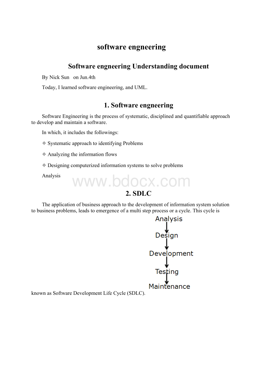
4.ProjectLifeCycle
Thecommonprojectlifecyclewilllikeflowbelow:
5.UML
UnifiedModelingLanguage
(UML)isastandardizedgeneral-purpose
modelinglanguage
inthefieldof
object-oriented
softwareengineering.Thestandardismanaged,andwascreatedby,theObjectManagementGroup.
UMLincludesasetofgraphicnotationtechniquestocreate
visualmodels
of
software-intensivesystems.
TheUMLcombinesthebestofthebestfrom:
✧DataModelingconcepts(EntityRelationshipDiagrams)
✧BusinessModeling(workflow)
✧ObjectModeling
✧ComponentModeling
5.1.UsageofUML
WecanuseUMLto
✧Displaytheboundaryofasystemanditsmajorfunctionsusingusecasesandactors
✧Illustrateusecaserealizationswithinteractiondiagrams
✧Representastaticstructureofasystemusingclassdiagrams
✧Modelthebehaviorofobjectswithstatetransitiondiagrams
✧Revealthephysicalimplementationarchitecturewithcomponent&
deploymentdiagrams
5.2.UseCaseDiagrams
Ausecaseisasetofscenariosthatdescribinganinteractionbetweenauserandasystem.
Ausecasediagramdisplaystherelationshipamongactorsandusecases.
Thetwomaincomponentsofausecasediagramareusecasesandactors.
Anactorisrepresentsauseroranothersystemthatwillinteractwiththesystemyouaremodeling.
Ausecaseisanexternalviewofthesystemthatrepresentssomeactiontheusermightperforminordertocompleteatask.
Usecasesareusedinalmosteveryproject.
Theyarehelpfulinexposingrequirementsandplanningtheproject.Duringtheinitialstageofaprojectmostusecasesshouldbedefined,butastheprojectcontinuesmoremightbecomevisible.
5.3.SequenceDiagrams
Asequencediagramisaninteractiondiagramthatfocusesonthetime-orderingofmessages.Itrepresentstheinteractionbetweendifferentobjectsinthesystem.
Sequencediagramsdemonstratethebehaviorofobjectsinausecasebydescribingtheobjectsandthemessagestheypass.
thediagramsarereadlefttorightanddescending.
Theexamplebelowshowsanobjectofclass1startthebehaviorbysendingamessagetoanobjectofclass2.
Messagespassbetweenthedifferentobjectsuntiltheobjectofclass1receivesthefinalmessage.
5.4.ClassDiagrams
Classdiagramsarewidelyusedtodescribethetypesofobjectsinasystemandtheirrelationships.Classdiagramsmodelclassstructureandcontentsusingdesignelementssuchasclasses,packagesandobjects.Classdiagramsdescribethreedifferentperspectiveswhendesigningasystem,conceptual,specification,andimplementation.Theseperspectivesbecomeevidentasthediagramiscreatedandhelpsolidifythedesign.ThisexampleisonlymeantasanintroductiontotheUMLandclassdiagrams.IfyouwouldliketolearnmoreseetheResourcespageformoredetailedresourcesonUML.
Classesarecomposedofthreethings:
aname,attributes,andoperations.
Belowisanexampleofaclass:
Classdiagramsalsodisplayrelationshipssuchascontainment,inheritance,associationsandothers.
Belowisanexampleofanassociativerelationship:
TheclassOrderisassociatedwiththeclassCustomer.
Themultiplicityoftheassociationdenotesthenumberofobjectsthatcanparticipateintherelationship.1
Forexample,anOrderobjectcanbeassociatedtoonlyonecustomer,butacustomercanbeassociatedtomanyorders.
Anothercommonrelationshipinclassdiagramsisageneralization.
Ageneralizationisusedwhentwoclassesaresimilar,buthavesomedifferences.
Lookatthegeneralizationbelow:
InthisexampletheclassesCorporateCustomerandPersonalCustomerhavesomesimilaritiessuchasnameandaddress,buteachclasshassomeofitsownattributesandoperations.
TheclassCustomerisageneralformofboththeCorporateCustomerandPersonalCustomerclasses.ThisallowsthedesignerstojustusetheCustomerclassformodulesanddonotrequirein-depthrepresentationofeachtypeofcustomer.
Nowgivethewholeclassdiagramofthisexample:
5.5.StateDiagrams
Statediagramsareusedtodescribethebehaviorofasystem.
Statediagramsdescribeallofthepossiblestatesofanobjectaseventsoccur.
Eachdiagramusuallyrepresentsobjectsofasingleclassandtrackthedifferentstatesofitsobjectsthroughthesystem.
BelowisanexampleofastatediagrammightlooklikeforanOrderobject.
WhentheobjectenterstheCheckingstateitperformstheactivity"
checkitems."
Aftertheactivityiscompletedtheobjecttransitionstothenextstatebasedontheconditions[allitemsavailable]or[anitemisnotavailable].
Ifanitemisnotavailabletheorderiscanceled.
Ifallitemsareavailablethentheorderisdispatched.
WhentheobjecttransitionstotheDispatchingstatetheactivity"
initiatedelivery"
isperformed.
AfterthisactivityiscompletetheobjecttransitionsagaintotheDeliveredstate.
5.6.ActivityDiagram
Activitydiagramsdescribetheworkflowbehaviorofasystem.
Activitydiagramsaresimilarto
statediagrams
becauseactivitiesarethestateofdoingsomething.
Thediagramsdescribethestateofactivitiesbyshowingthesequenceofactivitiesperformed.
Activitydiagramscanshowactivitiesthatareconditionalorparallel.
Belowisapossibleactivitydiagramforprocessinganorder.
Thediagramshowstheflowofactionsinthesystem'
sworkflow.
Oncetheorderisreceivedtheactivitiessplitintotwoparallelsetsofactivities.
Onesidefillsandsendstheorderwhiletheotherhandlesthebilling.
OntheFillOrderside,themethodofdeliveryisdecidedconditionally.
DependingontheconditioneithertheOvernightDeliveryactivityortheRegularDeliveryactivityisperformed.
Finallytheparallelactivitiescombinetoclosetheorder.
5.7.PhysicalDiagrams
Therearetwotypesofphysicaldiagrams:
deploymentdiagramsandcomponentdiagrams.Deploymentdiagramsshowthephysicalrelationshipbetweenhardwareandsoftwareinasystem.Componentdiagramsshowthesoftwarecomponentsofasystemandhowtheyarerelatedtoeachother.Theserelationshipsarecalleddependencies.
Thecombineddeploymentandcomponentdiagramabovegivesahighlevelphysicaldescriptionofthecompletedsystem.
ThediagramshowstwonodeswhichrepresenttwomachinescommunicatingthroughTCP/IP.
Component2isdependentoncomponent1,sochangestocomponent2couldaffectcomponent1.Thediagramalsodepictscomponent3interfacingwithcomponent1.
Thisdiagramgivesthereaderaquickoverallviewoftheentiresystem.
6.Exercise
InordertomasterUMLbetter,Itakeanexampleforexercise.HereisacaseaboutHomeLoan.TheHomeLoanCustomerentersallthenecessarydetailsintheformtoapplyforaloanwiththesystem.
6.1.E-RDiagram
Insoftwareengineering,anentity-relationshipmodelisanabstractandconceptualrepresentationofdata.Entity-relationshipmodelingisadatabasemodelingmethod,usedtoproduceatypeofconceptualschemaorsemanticdatamodelofasystem,oftenarelationaldatabase,anditsrequirementsinatop-downfashion.Diagramscreatedbythispro
 升级会员
升级会员 