MT6752 Power Deliver NetworksWord下载.docx
《MT6752 Power Deliver NetworksWord下载.docx》由会员分享,可在线阅读,更多相关《MT6752 Power Deliver NetworksWord下载.docx(15页珍藏版)》请在冰豆网上搜索。

RXD
RFIQandBSIControl
SPIandAUDI/F
DVDD_DVFS
LDOSandBucks
I2CandBC1.1
TRX
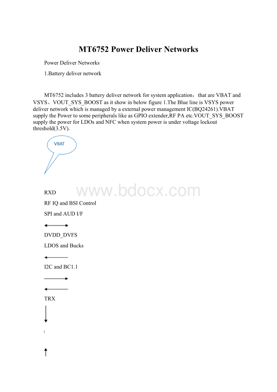
Figure1VBATPowerdelivernetwork
Powerpathmanagementforsystemload
MT6752solutionuseaexternalpowermanagementICtofinishsystempowerpathmanagementfrombatteryorchargersource.Asitshowsinthefigure2,therearedifferentpathtosystemloadwhensystempowersourcechangesfrombatterytocharger.
ThefirstpathisthatbatteryoutputpowertosystemloadwhenVBAT>
3.6V.ThePFETisonopendrainstate(VGS=0V)withoutbattery,whenbatterypluginbutnotchargerinPFETturnonandsystempowersourcedfrombattery.Atthetime,systemloadcurrentpathisISYS’,VSYS=VBAT.
Ifthebatteryvoltagefallsto3.5V,atthetimethechargerpluginaspowersouce,VSYSisregulatedto3.6Vtomaintainthesystemoutputevenwithadeeplydischargedorabsentbattery.Inthismode,theVSYSvoltageisregulatedbythebuckconverterandthebatteryPFETislinearlyregulatedtoregulatethechargecurrentintothebattery.ThecurrentfromthesupplyissharedbetweenchargingthebatteryandpoweringthesystemloadatVSYS.AsshowonFigure2,IIN=ISYS+IBAT.
Thedynamicpowerpathmanagement(DPPM)circuitrymonitorsthecurrentlimitscontinuouslyandiftheVBATfallsto3.5V,itadjustschargecurrenttomaintaintheminimumsystemvoltageandsupplytheloadonVSYS.Ifthechargecurrentisreducedtozeroandtheloadincreasesfurther,itenterthesupplementmode.Duringthesupplementmode.PFETisturnedonwhilethebatterysupplementsthesystemload.
IBAT
ISYS’
ISYS
IIN
Figure2Powerpathofsystemload
Figure3ExampleDPPMResponse(VSupply=5V,VBAT=3.1V,1.8AInputcurrentlimit)
BatteryConnected
Whenthebatteryisconnectedwithnoinputsource,thebatteryFETisturnedon.AfterthebatteryrisesaboveVBATUVLO=2.4V~2.6Vandthedeglitchtime,tDGL(BAT)=1.2ms,theVSYSoutputstartstorise.Inthismode,thecurrentisnotregulated;
however,thereisashortcircuitcurrentlimit.Iftheshortcircuitlimit(ILIM(DISCHG)=4~6A)isreachedforthedeglitchtime(tDGL(SC)=250us),thebatteryFETisturnedofffortherecoverytime(tREC(SC)=2S).Aftertherecoverytime,thebatteryFETisturnedontotestandseeiftheshorthasbeenremoved.Ifithasnot,theFETturnsoffandtheprocessrepeatsuntiltheshortisremoved.ThisprocessprotectstheinternalFETfromovercurrent.
Fromfigure3tofigure5,Whenbatteryisremovedbutchargersourcesintosystemload,thereisaPWMsignaldutycycleisabout83%onBATpin,soVGSisabout0V,FETisonopendrainstate.Afterbatteryconnected,FETisturnedonandregulatedcurrenttobattery.
Figure3startupwithnobattery
Figure4BatteryDetection
Figure5BatteryRemoval
SystemBoostforUVLO
MT6752usesanexternalDC/DCconvertertoextendthebatteryrun-timeandovercomesinputcurrentandvoltagelimitationsofthepoweredsystem.Whenthebatteryisatagoodstateofcharge(above3.5V),aintegratedNMOSswitchwouldturnonthepath(Figure6Greenline)toconnectsbatteryasLDOsandNFCpower.Ifthebatteryvoltagelowerthansystemminimumvoltage(below3.5V),theNMOSswitchturnoffandenterintoboostmode(Figure6Blueline)toutilizethefullbatterycapacity.Asitshowinfigure6,theboostrequireitsminimuminputvoltageis2.3VanditextendthevoltagelimitationsofLDOsandNFCinputpower.
AsFigure6shows,ItneedstoaddaschottkybetweenVSYSandVOUT_SYS_BOOSTtoensureVSYSalwayspowerforLDOsandNFCpowerwhenDC/DCconverterstartsup
Figure6Systemlowvoltageboostcircuit
2.CPUcorepower
2phaseBuckforAPcore
AexternalDC/DCisaddtosupplypowerofMT6752APcoresandimplementsDVFS,thevoltagerangeis0.6V~1.31V.Asitshowsinfigure7,theexternalDC/DChas2phasebucksconnectedtoMT6752APcorepowertorunDVFSfunctionforlowpowercondition.WhenCPUslowdown,thepowerlevelwillstepdownaccordingtocorefrequency.WhenCPUcoreswouldbeactive,buckconvertorrisespowerlevelatfirstandthenCPUcoresfrequencystepup.
ThepowerlevelofbuckconvertorisprogrammedbyI2Cbus,asitshowsonfigure7itprogramsthedividerresistanceonconvertorfeedbackcircuittosetvoltagelevel.
Figure72PhaseBuck
AsFigure8,itistheexampleofoutputvoltagedifferentialsensing.ThedifferentialsensecomparesahighaccuracyVIDDACandaprecisionreferencetoimplementalowoffseterroramplifier.Thismaintainsaworst-casespecificationof±
9.5mVdifferentialsensingerrorovertheirfulloperatingoutputvoltageandtemperaturerange.TheoutputvoltageissensedbetweentheFBpinandtheFBRTNpin.FBshouldbeconnectedtotheregulationpoint,usuallytheremotesensepinofthemicroprocessor.FBRTNshouldbeconnecteddirectlytotheremotesensegroundpoint.TheinternalVIDDACandprecisionreferencearereferencedtoFBRTN,whichhasaminimalcurrentof100μAtoallowaccurateremotesensing.TheinternalerroramplifiercomparestheoutputoftheDACtotheFBpintoregulatetheoutputvoltage.
Figure.8AExampleofFeedbackCircuit
ModemCorePowerandGPUpower
MT6325internalbuckconvertorVCORE1/2andVGPU,supplypowerforModemcoreandGPUcore.
Thebuckconvertorsuseaproprietarynon-linear,fixed-frequencyPWMmodulatortodeliverafastloadtransientresponse,whilemaintainingaconstantswitchingfrequencyoverawiderangeofoperatingconditions.Althoughthistypeofoperationnormallyresultsinaswitchingfrequencythatvarieswithinputvoltageandloadcurrent,aninternalfrequencyloopholdstheswitchingfrequencyconstantoveralargerangeofinputvoltagesandloadcurrents.Forverylightload,buckconvertoroperatesinDiscontinuousCurrentDiode(DCM)single-pulsePFM,whichproduceslowoutputripple.TransitionbetweenPWMandPFMisrelativelyseamless,providingasmoothtransitionbetweenDCCMandCCMModes.
Whileloadcurrentisbelow100mA,lightloadcondition,convertorsgointoPFMandtransittoPWMwhenloadcurrentisabove100mA.FromFigure8andFigure9,theouputrippleisabout0.75MHZ~2MHZ,rippleswingisabout20mVinPFMmodewhenVintransitsbetween3Vto3.6Vandloadcurrenttransitbetween500mAto50mA.
Figure9.3Vto3.6VVinTransientcombinedwith500mAto50mALoadTransient
Figure10.3.6Vto3VVinTransientcombinedwith50mAto500mALoadTransient
Fromfigure10andfigure11,loadcurrentis200mAand800mA,heavyloadcondition,convertorsenterPWMmode,theoutputvoltageissmoothandwithnoripple.
Figure11.3Vto3.6VVinTransientcombinedwith800mAto200mALoadTransient
Figure12.3Vto3.6VVinTransientcombinedwith200mAto800mALoadTransient
AutoPFM/PWMtransitionishigherefficiencythanforcedPWMthroughfromlightloadtoheavyloadofsystem.Especially,PFMmodegivesconvertorahighefficiencyonlightload.
Figure13.Efficency,AutoPWM/PFMvs.ForcedPWMatVout=0.75V
Figure14.Efficency,AutoPWM/PFMvs.ForcedPWMatVout=1.2V
3.MemoryPower
InternalSRAMpower
BBhasinternalSRAMforoperationbuffer.DVDD_SRAMsuppliesthepowerfortheinternalSRAMpower.
DDRpowernetwork
VIO18_PMU(1.8V)suppliesDDRcore1power.VDRAM_PMU(1.1V/1.2V/1.35V/1.5V,2000mA)suppiesDDRcoreandI/OpowerofBB.Alsoitsuppliescore2powerandI/Ovoltage,CAcontrollerofDDR.
eMMCpowernetwork
VEMC_3V3_PMU(3/3.3V,400mA)supplieseMMCcorevoltageofeMCP,whichisNANDintegratedwithacontrollerforeMMCboot.VIO18_PMU(1.8V)supplieseMMCI/OvoltageonbothBBandeMCPside.AndalsoVIO18_PMUsuppliesMSDC0controllerpowerofBB.
VMC(1.8V/3.3V,200mA)suppliesMSDC1controllerandI/OvoltageofBBside.VMCH(3/3.3v,800mA)suppliescoreandI/Opowerofexternalmemorycard.Fromfigure15,VCCQ(I/OVoltage)doesnotsupport3.3VrangeWheneMMCbusclockspeedis200MHZ.
Figure15eMMCvoltagecombinationsfromJEDEC
4.RFPower
Thereare5powersforRFtransceiverandPA,VRF18_PMU(1.825V,450Ma)forMT6169,VRF18_1_PMU(1.825V,200mA)forMT6165.VPA_PMU(0.5V~3.4V,600mA)suppliesforSKY77621Whichisahybridmultimodemultiband(MMMB)PowerAmplifierModule(PAM)thatsupports2.5G/3G/4Ghandsets,andoperatesefficientlyinGSM,EGPRS,EDGE,WCDMA,TD-SCDMA,andLTEmodes.AndalsoVPA_PMUsuppliesforSKY77778,WhichisPowerAmplifierModuleforLTEFDDBand7(2500–2570MHz),andTDDBands38/41(2496–2690MHz),Band40(2300–2400MHz),AXGPBand(2545–2575MHz).VTCXO_1_PMU(2.8V,40mA)suppliespowerforMT616926Mclockblock.VTCXO_2_PMU(2.8V,40mA)suppliespowerforMT616526Mclockblock.