精品自制激光测距仪.docx
《精品自制激光测距仪.docx》由会员分享,可在线阅读,更多相关《精品自制激光测距仪.docx(14页珍藏版)》请在冰豆网上搜索。
精品自制激光测距仪
激光:
基于摄像头的激光测距仪
2009-02—2321:
45
介绍
有很多现成的测距组件包括超声波、红外线、甚至是激光测距仪。
这些设备运行的很好,但是对于飞行机器人来说,重量是一个主要考虑因素。
一个可行的办法是增加现有组件的功能,并安装在机身上.例如微型空中机器人的有效载荷是100g。
它能利用USB连接的摄像头(或mini无线摄像头)执行视觉任务,例如避障等。
更好的是,如采用两个摄像头,能提供立体的机器视觉,这样能增强避障性能,因为双镜头提供了视觉深度。
但缺点是需要增加另外一个摄像头的重量.这篇文章就是讨论如何利用一个激光笔和一个摄像头来提供一个单镜头机器视觉和测距的.
这个项目很大一部分是基于下面这个教程的
http:
//www.eng。
buffalo。
edu/ubr/ff03laser。
php
工作原理
下图显示了如何将激光点投射到目标物上,并在摄像头上显示.摄像头和激光点的距离是可以通过计算而得出的.公式很简单,因此这个技术在需要很快运行的机器视觉应用上是适合的.
介绍一下工作原理.一束激光被投射到目标物上,并在摄像头上被显示。
激光束被认为是理想的平行于摄像头的中心光轴。
激光点由摄像头的其余部分所捕获。
一个简单的计算就是寻找最亮点。
如果设激光点就是这个场景的最亮点(似乎在室内我的激光发射器确实是最亮的),那么这个点的位置在图帧中的位置是确定的.然后我们只需要计算这个点在沿着y轴的距离,就能计算出目标物离摄像头的距离,激光点距离中心越近,离目标物越远。
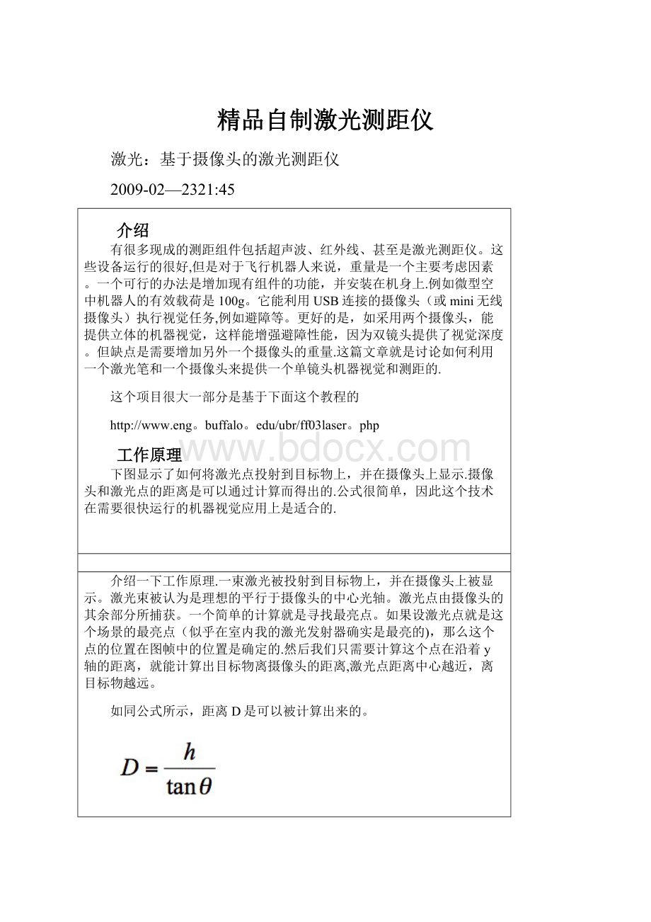
如同公式所示,距离D是可以被计算出来的。
为了计算这个等式,我们需要知道激光器和摄像头之间的距离h,这是个常数,还有角度,角度可以计算。
其中:
pfc=从焦平面到中心的像素数量
rpc=单个像素的弧度
ro=弧度补偿(弥补对齐错误)代入上式,我们得到:
这样,从图像中就能将焦平面到激光点像素数计算出来。
那其他的常数怎么办呢?
我们需要执行一个校准来得到这些数据。
为了校准这个系统,我们需要收集一系列测量的数据,每次测得的目标物的距离和这个激光点离中心点的像素数。
数据如下
校正数据
pixelsfromcenter
actualD(cm)
103
29
81
45
65
58
55
71
49
90
45
109
41
127
39
159
37
189
35
218
使用下面的公式,我们能够利用激光器和摄像头之间的距离h和真实距离计算出真实的角度:
θactual=真实角度
Dactual=真实距离(测量得出)
现在我们有了公式中的每个数值,我们可以利用一个关系式来计算点离中点的像素数。
我用了一个线性关系式。
这个公式看起来很有用,……
从我的校正数据中,我计算出:
Offset(ro)=—0.056514344radians
Gain(rpc)=0。
0024259348radians/pixel
使用:
下表是列举了根据上面ro和rpc值计算出的距离值,实际距离值和误差:
RoboticFan
实际和计算的测量数据
pixelsfromcenter
calcD(cm)
actualD(cm)
%error
103
29.84
29
2.88
81
41.46
45
—7。
87
65
57.55
58
-0。
78
55
75。
81
71
6。
77
49
93.57
90
3。
96
45
110。
85
109
1.70
41
135。
94
127
7.04
39
153.27
159
—3.60
37
175.66
189
—7.06
35
205.70
218
—5。
64
所需零部件
我的测距仪没有多少部件。
我使用一块硬纸板来固定激光发射器和摄像头.摄像头和激光发射器被平行的布置在一起.
我组装的测距仪是这样的
软件
我通过两个方式编写了这个软件,一个是vc++,一个是VB。
你能发现VB版本的软件会比VC++的软件更容易一些,但是各有取舍。
VC++版本能够自由的加入其他软件中?
VB版本需要第三方软件支持(在VisualStudio中)
VisualBasic
vb_laser_ranger.zip
这里可以下载到我的VB版本软件.
要使用上面的程序,你必须要安装VideoOCXActiveX控件
主程序如下:
PrivateSubexit_Click()
'onlyifrunning.。
.
If(Timer1。
Enabled)Then
Timer1。
Enabled=False’StopTimer
VideoOCX。
Stop
VideoOCX.CloseEndIfEnd
EndSub
PrivateSubStart_Click()'InitVideoOCXControl,allocatememoryandstartgrabbingIf(NotTimer1.Enabled)Then
Start.Caption=”Stop”'DisableinternalerrormessagesinVideoOCX
VideoOCX。
SetErrorMessagesFalse'Initcontrol
If(NotVideoOCX。
Init)Then
'Initfailed。
Displayerrormessageandendsub
MsgBoxVideoOCX。
GetLastErrorString,vbOKOnly,”VideoOCXError”
End
Else
'Allocatememoryforglobalimagehandle
capture_image=VideoOCX。
GetColorImageHandle
’result_image=VideoOCX_Processed.GetColorImageHandleTimer1.Enabled=True'Startcapturetimer’StartCapturemode
If(NotVideoOCX.Start)Then
'Startfailed。
Displayerrormessageandendsub
MsgBoxVideoOCX.GetLastErrorString,vbOKOnly,”VideoOCXError”
End
EndIf
EndIf
Else
Start.Caption="Start"
Timer1.Enabled=False'StopTimer
VideoOCX.Stop
VideoOCX。
Close
EndIfEndSub
PrivateSubTimer1_Timer()
'Timerforcapturing—handlesvideoOCXTools
DimmatrixAsVariant
Dimheight,widthAsInteger
Dimr,cAsInteger
Dimmax_r,max_cAsInteger
Dimmax_redAsInteger
Dimgain,offsetAsVariant
Dimh_cmAsVariant
DimrangeAsInteger
Dimpixels_from_centerAsInteger’Calibratedparameterforpixeltodistanceconversion
gain=0.0024259348
offset=—0.056514344
h_cm=5。
842max_red=0’Captureanimage
If(VideoOCX.Capture(capture_image))Then'VideoOCX。
Showcapture_image’Matrixtransformationinitialization
matrix=VideoOCX。
GetMatrix(capture_image)height=VideoOCX.GetHeight
width=VideoOCX.GetWidth’Imageprocessingcode’Thelaserdotshouldnotbeseenabovethemiddlerow(withalittlepad)
Forr=height/2-20Toheight—1’Ourphysicalsetupisroughlycalibratedtomakethelaser
'dotinthemiddlecolumns。
。
.dontbotherlookngtoofaraway
Forc=width/2-25Towidth/2+24’Lookforthelargestredpixelvalueinthescene(redlaser)
If(matrix(c,r,2)〉max_red)Then
max_red=matrix(c,r,2)
max_r=r
max_c=c
EndIf
Nextc
Nextr’Calculatethedistanceforthelaserdotfrommiddleofframe
pixels_from_center=max_r-120
’Calculaterangeincmbasedoncalibratedparameters
range=h_cm/Tan(pixels_from_center*gain+offset)
’Printlaserdotpositionrowandcolumntoscreen
row_val。
Caption=max_r
col_val.Caption=max_c’Printrangetolaserilluminatedobjecttoscreen
range_val.Caption=range'Drawaredverticallinetointersecttarget
Forr=0Toheight-1
matrix(max_c,r,2)=255
Nextr’Drawaredhorizontallinetointersecttarget
Forc=0Towidth—1
matrix(c,max_r,2)=255
NextcVideoOCX。
ReleaseMatrixToImageHandle(capture_image)RoboticFanEndIfVideoOCX。
Showcapture_image
EndSub
截屏如下:
VisualC++
我的代码是基于PaulOh教授的教程。
你需要注意,当跟进这个教程的时候,一些必要的文件也许不再正常连接或丢失,他们可以在下面的位置下载。
qcsdk.exe
qc543enu。
exe
根据TRIPOD的教程的说明,可以在其源程序中插入一段用户自己的图像处理代码,在这里,我插入了下面的代码:
voidCTripodDlg:
:
doMyImageProcessing(LPBITMAPINFOHEADERlpThisBitmapInfoHeader)
{
//doMyImageProcessing:
Thisiswhereyou'dwriteyourownimageprocessingcode
//Task:
Readapixel'sgrayscalevalueandprocessaccordingly
unsignedintW,H;//WidthandHeightofcurrentframe[pixels]
unsignedintrow,col;//Pixel'srowandcolpositions
unsignedlongi;//Dummyvariableforrow-columnvector
unsignedintmax_row;//Rowofthebrightestpixel
unsignedintmax_col;//Columnofthebrightestpixel
BYTEmax_val=0;//Valueofthebrightestpixel
//Valuesusedforcalculatingrangefromcapturedimagedata
//thesevaluesareonlyforaspecificcameraandlasersetup
constdoublegain=0。
0024259348;//GainConstantusedforconverting
//pixeloffsettoangleinradians
constdoubleoffset=—0.056514344;//OffsetConstant
constdoubleh_cm=5.842;//Distancebetweencenterofcameraandlaser
doublerange;//Calculatedrange
unsignedintpixels_from_center;//Brightestpixellocationfromcenter
//notbottomofframecharstr[80];//Toprintmessage
CDC*pDC;//Devicecontextneedtoprintmessage
RoboticFan
W=lpThisBitmapInfoHeader—>biWidth;//biWidth:
numberofcolumns
H=lpThisBitmapInfoHeader->biHeight;//biHeight:
numberofrowsfor(row=0;rowfor(col=0;col〈W;col++){
//Recalleachpixeliscomposedof3bytes
i=(unsignedlong)(row*3*W+3*col);//Ifthecurrentpixelvalueisgreaterthananyother,itisthenewmaxpixel
if(*(m_destinationBmp+i)>=max_val)
{
max_val=*(m_destinationBmp+i);
max_row=row;
max_col=col;
}
}
}
//Aftereachframe,resetmaxpixelvaluetozero
max_val=0;
for(row=0;rowfor(col=0;coli=(unsignedlong)(row*3*W+3*col);//Drawawhitecross-hairoverbrightestpixelintheoutputdisplay
if((row==max_row)||(col==max_col))
*(m_destinationBmp+i)=
*(m_destinationBmp+i+1)=
*(m_destinationBmp+i+2)=255;
}
}
//Calculatedistanceofbrightestpixelfromcenterratherthanbottomofframe
pixels_from_center=120-max_row;
//Calculaterangeincmbasedonbrightpixellocation,andsetupspecificconstants
range=h_cm/tan(pixels_from_center*gain+offset);
//Toprintmessageat(row,column)=(75,580)
pDC=GetDC();
//Displayframecoordinatesaswellascalculatedrange
sprintf(str,"MaxValueatx=%u,y=%u,range=%fcm”,max_col,max_row,range);
pDC—〉TextOut(75,580,str);
ReleaseDC(pDC);
}
完整的代码可以在下面下载到:
LaserRange.zip
可执行文件可在下面下载到:
LaserRange.exe
注意,为了执行这个文件,你可能需要qcsdk和qc543这两个驱动文件。
下面是摄像头激光测距仪的工作截图,注意它是如何工作的。
在第二个例子中,有两个激光点,其中的一个是激光点在摄像头里面的反射,这个反射点由于没有那么强烈的,所以不适用于运算法则.
将来的工作
一个重要的改进就是将点改为线,这样可以计算每个光柱的距离而不是单个的光柱。
这样的设置可以使车辆能够探测最大的前进距离,同样的,障碍物的最小距离也可以被探测到。
 升级会员
升级会员 