PSCAD例子的学习对部分example的解释.docx
《PSCAD例子的学习对部分example的解释.docx》由会员分享,可在线阅读,更多相关《PSCAD例子的学习对部分example的解释.docx(35页珍藏版)》请在冰豆网上搜索。
PSCAD例子的学习对部分example的解释
PSCAD例子的学习笔记
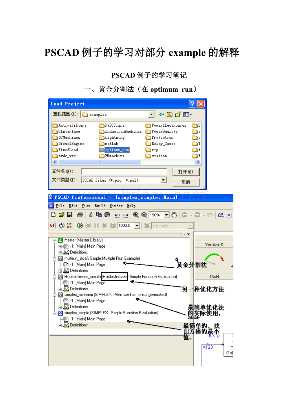
一、黄金分割法(在optimum_run)
二、电能质量(在PowerQuality中)
软件的英文说明:
ThisapplicationexampleisbasedonacaseorigionallycreatedattheManitobaHVDCResearchCentrebyDr.M.Reformat,inManitoba,Canada.
ThiscaseillustratestheuseofaSTATCOMtoprovideactivefilteringfortheacsideofa6-pulseconvertersystem.TheActivefilterisconnectedthrougha20kVA,Y-Ytransformertoa200V,50Hz,3-Phasebus,witha6-pulseconverterload
REFERENCE:
H.FujitaandH.Akagi,
'APracticalApproachtoHarmonicCompensation
inPowerSystems-SeriesConnectionofPassive
andActiveFilters',IEEETrans.onInd.Applications,
vol.27,No.6,Nov/Dec1991,pp.1020-1025
RevisedbyJ.E.Nordstrom-September2000
软件的英文说明。
ThisapplicationexampleisbasedonacaseorigionallycreatedatManitobaHydro,inManitobaCanada.
Theproblemwasthatfarmanimals,duringwintermonths,wereexperiencinga"tinglevoltage",duetosuspectedpoorgroundingonthelocalgroundgrid.
UsingPSCAD,theengineerswereabletosimulatethelocalsystemanddeterminethatthegroundingproblemwasatleastpartiallyrelatedtogroundrodresistance.Duringthewintermonths,thegroundconductivityispoor,resultinginapoorconnectionbetweenthegroundrodsandearth.
Whilethiscaseisrunning,youcanadjustthegroundrodresistance.Noticethechangeinvoltageacrossthecow!
RevisedbyJ.E.Nordstrom-July2000
三、继电保护
Case1:
-TwoThevinenImpedancesourcesconnectedviaone100kmtransmissionline.
(双电源系统通过100km长度相连)
-Systemvoltageis230kVsettableviasourceequivalents.
(230kV)
-Simulatestwosubstationsconnectedviaonetransmissionline.
(仿真两个变电所之间的传输线路)
-Fourfaultpositionsforfullfaultcontrolaheadandbehindstationrelays.
(设计了四个故障点)
-Twobreakersareindependentlytimedcontrolled.(Defaultisclosed).
(两侧的断路器可以通过时间,默认是合上的)
-Independentbreakerpoletrippingispossible.
(可以实现分相操作)
CASE2:
多个故障点。
其它一样
CASE3:
双回线
CASE4:
双回线的不同故障点
CASE5:
双回线的不同故障点再加支出一条线路
CaseDescription:
-TwoThevinenImpedancesourcesconnectedvia
transmissionlinesandaT-tap.
-Onetransmissionlineterminatedwithatransformer
ofconfigurablesizeandtype.
-Systemvoltageis230kVsettableviasourceequivalents.
-Simulatesthreesubstationsconnectedviathreetransmissionlines.
-Eight(8)faultpositionsforfullfaultcontrolaheadandbehindstationrelays.
-Fivebreakersareindependentlytimedcontrolled.(Defaultisclosed).
-Independentbreakerpoletrippingispossible.
CASE6:
双回线的不同故障点再加支出一条线路
与CASE5类似,细节有所不同。
故障点任意设置。
CaseDescription:
DOUBLELINEWITHAT-TAP
-TwoThevinenImpedancesourcesconnectedvia
transmissionlinesandaT-tap.
-Onetransmissionlineterminatedwithatransformer
ofconfigurablesizeandtype.
-Systemvoltageis230kVsettableviasourceequivalents.
-Simulatesthreesubstationsconnectedviafourtransmissionlines.
-Ninefaultpositionsforfullfaultcontrolaheadandbehindstationrelays.
-FaultscanbeplacedMidlineonLine1,Line2andLine3
-UsermusttakeCaretoensurethesumofthesections,T1throughT6sum
tothelengthofthelinestheyaresimulating.
-Fivebreakersareindependentlytimedcontrolled.(Defaultisclosed).
-Independentbreakerpoletrippingispossible.
CASE7:
联络变压器
CaseDescription:
-TwoThevinenImpedancesourcesconnectedviaaD-Ytransformer.
-Systemvoltageis230kV/25kVsettableviasourceequivalents.
-Simulatestwosystemswithafeederload.
-Fourfaultpositionsforfullfaultcontrolaheadandbehindstationrelays.
-Threebreakersareindependentlytimedcontrolled.(Defaultisclosed).
-Independentbreakerpoletrippingispossible.
CASE8:
三绕组变压器
CaseDescription:
-TwoThevinenImpedancesourcesconnectedviaaY-D-Ytransformer.
-Faultscanbeappliedtothe10kVDeltatertiarywinding
-Systemvoltageis230kV/25kVsettableviasourceequivalents.
-Simulatestwosystemswithafeederload.
-Fivefaultpositionsforfullfaultcontrolaheadandbehindstationrelays.
-Fivebreakersareindependentlytimedcontrolled.(Defaultisclosed).
-Independentbreakerpoletrippingispossible.
CASE9:
与SEL321Relay相关的模型
ThisexamplesystemistakenfromtheSEL321RelayInstructionManual,Chapter5.
ThetransmissionlinemodelsarebasedoninputtingR,X,andBdatamanually.
Linedataisenteredpermeter;therefore,thelengthsofthedifferent
linesectionsareadjustedsimplybychangingthelinelength.
四、(次同步机)SubSyncRes文件夹中内容
IEEEFIRSTBENCHMARKCASEFORSUB-SYNCHRONOUSRESONANCESTUDIES
ExampleCaseCharacteristics:
-FieldVoltageofSynchronousmachineheldatthesamevalue
-Mech.TorqueofSynchronousmachineheldattheinitialvalue
-Multimassenabledattime=1.4sec.Theinput"Mactiv"allowsthemultimasstobeenabledonlywhenthemachineisactive.Themultimassisinitializedwithsmoothedvalueofelectricaltorque"Testdy"fromthemachinemodel.
Reference:
IEEETransactionsonPowerApparatusandSystem,
Vol.96,No.5,October1977,pp.1565-1572.
五、(WINDFarm文件夹)风力发电机(异步机)
Thiscaseshowsainductiongeneratorbeingdrivenbyawindturbine.Theturbineiscontroledbyawindgovernor.The'windsource'isusedtomodelwindspeedfluctuations.
学习心得(2012-2-21):
这个风机由三个部分组成:
一是风机(相当于发电厂是的汽轮机),二是调速器(相当于汽轮机的气门控制装置,三是发电机(实际上是鼠笼电动机)。
1、风机的设置
上述参数中,Vw是风速,属于外部输入参数,模型前面的就有风速的调节模块,本例中风速一定。
W是电机的机械速度。
这个W的单位是(rad/s)
因此,在“模拟风机的机械速度”处,w是电动机的输出速度。
OutputSpeed是一个标么值,将其乘以2*PI*f再除以极对数。
变所W。
还有一个输入就是Beta,就是pitchangle桨距角(可能叫法不对),我的理解是风机叶片的角度,相当于船的桨的吃水角度。
输出Tm给电机,输出P看看的。
以上调整风机的叶片长度、空气密度、齿轮箱效率等等参数。
2、调速器的设置
PitchControl就是节距控制。
下图中的1.44是风机的要求功率(ref为参照的意思)。
Wref为电角速度。
对应于50Hz。
下图为比例积分调节,属于控制参数。
下图为速度阻尼参数,属于控制参数。
下图比较重要,是桨距角的调整。
3、鼠笼电机的设置
见电动机的控制W,S,T。
:
记住:
Aswitchtoselectspeedcontrolmode
(1)ortorquecontrolmode(0).本例中,在1s时,通过控制设置为“0”变成转矩控制,之前是速度控制。
T是风机传过来的。
对于模型的初步认识:
1)1s时,鼠笼电机转为转矩控制。
2)5s时。
进入桨距控制。
显示出通过控制桨距,满足了功率输出的需求。
六、(WINDFarm文件夹)风力发电机(同步机)
Thiscaseshowsasynchronousgeneratorbeingdrivenbyawindturbine.Theturbineiscontroledbyawindgovernor.The'windsource'isusedtomodelwindspeedfluctuations.
七、(WINDFarm文件夹)风力发电机并网(软起动)
八、Tutorial(教程)
1.Chatter波形的抖动的处理
DefinitionofChatter:
---------------------------
Anumericaloscillation(振荡,幅值不定)(everytimestep)invoriwhichiscausedbytrapezoidalintegration.(梯形积分)
Itisnotrealistic.
Voltagechatteroccurswheneveradisturbanceisappliedatanodetowhichonlyinductorsareconnected.
Currentchatteroccurswheneveradisturbanceisappliedatalocationwherecapacitorsareconnectedinaloop.
Chattercanbeinitiatedbyswitchingactions,orbystepsincurrentinjections(orvoltagesources).
Chatterisnotcausedbyinterruptioninthecurrentinaninductoratanon-zeropoint.
ChatterEliminationTechniques:
--------------------------------------------
解决方法
1)Adddampingresistors.Thismethodwillcausetheoscillationtodampoutwithinafewcycles,butitwilladdextradampingtothesolution.
2)CDA-CriticalDampingAdjustment.ThismethodeliminateschatterbychangingfromTrapezoidalIntegrationto2timestepsofrectangularintegration.Thiswillsolvethechatterproblem,but
thesolutionaccuracyisdegraded(albeitonlyforafewtimesteps)duetothelessaccurateintegrationapproximation.Rectangularintegrationcanalsobenumericallyunstable(whereastrapezoidal
isalwaysstable).
3)1/2StepInterpolation.Thismethodinterpolatesbetween0and1(to0.5),thenstepsfrom0.5to1.5(usingtheregulartrapezoidalmethod),andtheninterpolatesbackto1.0tocompletethetimestep.
4)RootMatching.Thisisanewintegrationtechniquewhichreplacesthestandardtrapezoidalintegrationalgorithm.Itdoesnotinitiatechatter,soaremovalprocessisnotrequired.
-Rootmatchingcanonlybeformulatedwherebranchescontainatleast2ormoreelements(ieRL,LC..)soisineffectiveforpureinductivenodeproblems.
-BranchessolvedwithRootMatchingcanbeintermixedinthesamesolutionwithbranchessolvedwithotherintegrationtechniques.
-RootMatchingisalwaysnumericallystable.
-RootMatchingisasefficient(ormoreefficient)numericallythantrapezoidalintegration.
2.HARMONICIMPEDANCEANDFFT(谐波负荷及在线快速傅丽叶FFT)
Asimplecaseillustratingapplicationofcurrentinjectionandtheon-lineFastFourierTransform.HarmoniccurrentsareinjectedatspecifiedfrequenciesandofequalmagnitudeintoanRLCnetworkwhoseresonantfrequencyis120Hz.ThevoltagedropoftheentireRLCnetworkisfedintoanonlineFastFourierTransformtodeterminethemagnitudesandphasesoftheharmonicspresent.
Totherightaretheharmonicmagnitudeandphasereadings.Theharmonicmagnitudeandphaseisdisplayedintheformofaphasormeter.Eachphasorrepresentsaharmonicincludingthefundamental.Clickingontheproperbuttoninthedisplayselectorwilldisplaythemagnitudeandphasefortheappropriateharmonicinthestatusbar.
3.INPUTCONTROLCOMPONENTS(引入控制模块)
Asimplecasewithsetofinputcontrolcomponentsneededforinteractivesimulation.
Theyareusedtomakechangesinsignalandparametervaluesatthetimeofsimulation.
4.SIMPLEGTODEVICEUSINGINTERPOLATION(对付自激电动势)
nterpolationisanintegralpartofEMTDCwhichallowsswitchingdevicestoswitchatanyinstantoftimeinsteadofonlyontheregulartimestepgrid.Thisallowstheuseofalargertimestepwithoutmissingcurrentzeroesorotherswitchinginstants.
Thiscircuitshowsthesimplestformofforcedcommutation.Adccurrentwillflowintotheinductor,slowingreachingitssteadystatecondition.Whenthegtodevice
 升级会员
升级会员 