卡特320d发动机c64中文资料.docx
《卡特320d发动机c64中文资料.docx》由会员分享,可在线阅读,更多相关《卡特320d发动机c64中文资料.docx(55页珍藏版)》请在冰豆网上搜索。
卡特320d发动机c64中文资料
C4.2andC6.4EnginesforCaterpillarBuiltMachines
EngineDesign
SMCS—1201
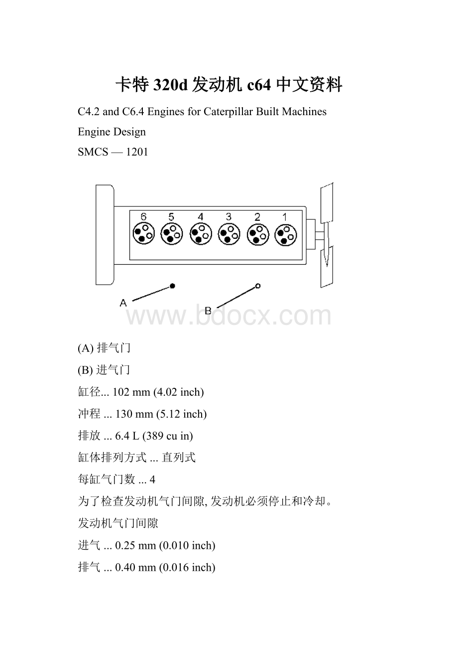
(A)排气门
(B)进气门
缸径...102mm(4.02inch)
冲程...130mm(5.12inch)
排放...6.4L(389cuin)
缸体排列方式...直列式
每缸气门数...4
为了检查发动机气门间隙,发动机必须停止和冷却。
发动机气门间隙
进气...0.25mm(0.010inch)
排气...0.40mm(0.016inch)
燃烧类型...直接燃烧
点火顺序...1-5-3-6-2-4
曲轴旋转的方向从飞轮往发动机直视
曲轴旋转方向......逆时针
注意:
从风扇端往飞轮端看发动机左端和右端,最前面的是1缸。
燃油喷油油路
接触高压燃油可能会导致渗透和烧伤.高压燃油喷射会导致火灾。
未遵守这些检查,维修和服务指示,可能会导致人身伤害或死亡。
(1)两头螺母扭矩...41±5N·m(30±4lbft)
(2)12颗螺丝扭矩...17.0±1.7N·m(150±15lbin)
(3)4颗螺丝扭矩...9±1N·m(80±9lbin)
(4)螺丝的扭矩...8.5±0.5N·m(75±4lbin)
(5)扭矩...25.0to27.5N·m(220to245lbin)
(6)4颗螺丝扭矩...34±4N·m(300±35lbin)
(7)6颗螺丝扭矩...15±2N·m(130±18lbin)
(8)2颗接头扭矩...25.0to27.5N·m(220to245lbin)
燃油喷油泵
1)电磁阀组件扭矩...70±5N·m(50±4lbft)
(2)2个堵头扭矩...60±6N·m(44±4lbft)
(3)堵头扭矩...15±2N·m(11±1lbft)
(4)使用以下步骤去拎紧螺丝:
1.螺丝拧紧到5N·m(45lbin).
2.拧螺丝角度到18.8±1.0度.
3.最后螺丝扭矩12±2N·m(105±18lbin).
(5)安装之前,用干净的机油去润滑这三个密封.
(6)两个堵头扭矩...40±3N·m(30±2lbft)
(7)这个螺丝扭矩...12±3N·m(105±27lbin)
(8)这个螺丝扭矩...9±1N·m(80±9lbin)
(9)5个螺丝扭矩...30±2N·m(22±1lbft)
(10)使用下面步骤去拎4颗螺丝:
1.螺丝拧紧到5N·m(45lbin).
2.拧螺丝角度到19.9±1.0degrees.
3.最后螺丝扭矩12±2N·m(105±18lbin).
(11)接头扭矩...25.0±2.5N·m(18±2lbft)
(12)接头扭矩...25.0±2.5N·m(18±2lbft)
(13)接头扭矩...25.0±2.5N·m(18±2lbft)
(14)接头扭矩...25.0±2.5N·m(18±2lbft)
喷油嘴
(2)夹具
(3)O型密封圈
(1)这个螺丝扭矩...29±3N·m(21±2lbft)
燃油滤芯座
(1)两个螺丝的扭矩...32±3N·m(285±27lbin)
(2)两个螺丝的扭矩...8.8±1.0N·m(80±9lbin)
摇臂轴
(1)Boreinrockerarmbushingforshaft...24.949to24.975mm(0.9822to0.9833inch)
(2)Diameterofrockerarmshaft...24.915to24.928mm(0.9809to0.9814inch)
Clearanceofrockerarmbushingandshaft
Minimum...0.021mm(0.0008inch)
Maximum...0.060mm(0.0024inch)
(3)Aligntheoilholesinrockerarmbushing(4)withtheoilholesintherockerarmwhentherockerarmbushingisreplaced.
(5)Torqueforsixbolts...18±2N·m(13±1lbft)
(6)Torqueforsixbolts...18±2N·m(13±1lbft)
(7)Torqueforbolt...74±5N·m(55±4lbft)
Turnthecrankshaftuntilthetimingmarkonthecrankshaftpulleyisalignedwiththepointeronthetiminggearhousinginordertoadjustthevalvelash.BoththeNo.1inletvalveandtheNo.1exhaustvalvepushrodsmustnotbeintensionagainsttherockerarms.
Inletvalvelash...0.25mm(0.010inch)
Exhaustvalvelash...0.40mm(0.016inch)
ValveMechanismCover
(1)Torquefor25bolts...18±2N·m(160±18lbin)
(2)Torquefor18bolts...17±2N·m(150±18lbin)
(3)Torqueforeightbolts...8.8±1.0N·m(80±9lbin)
CylinderHeadValves
(A)Diameterofthevalvehead
Inlet...34.5mm(1.36inch)
Exhaust...27.5mm(1.08inch)
(B)Diameterofthevalvestem
Inletvalve...6.6mm(0.26inch)
Exhaustvalve...6.6mm(0.26inch)
(C)Lengthofthevalve
Inletvalve...144.0mm(5.67inch)
Exhaustvalve...144.0mm(5.67inch)
(D)Widthofthevalveseat
Inlet...1.0mm(0.039inch)
Exhaust...1.2mm(0.047inch)
(E)Angleofvalveseatface
Inlet...30degrees
Exhaust...45degrees
CylinderHead
(1)Dimensionforthecylinderhead
Useastraightedgeandafeelergaugetocheckthecylinderheadforwarpage.
Flatnessofthecylinderheadovertotalspan...0.05mm(0.002inch)
Resurfacethecylinderheadifthewarpageexceedsthefollowingvalue....0.20mm(0.008inch)
Gasketthicknessofcylinderhead...1.70±0.05mm(0.067±0.002inch)
Note:
Therepairlimitofthecontactsurfaceofthegasketandtherepairlimitofthecylinderblocksurfaceis0.20mm(0.008inch).
Note:
Putcleanengineoilonthethreadsofthecylinderheadbolts.
Tightenthebolt1throughbolt26inthenumericalsequencethatisshowninIllustration2to137±5N·m(100±4lbft).
ExhaustManifold
(1)Torquefor13nuts...18±2N·m(13±1lbft)
Camshaft
1)Maximumpermissibletemperatureofthecamshaftgearforinstallationonthecamshaft...250°C(482°F)
NOTICE
Donotuseatorchtoheatthegear.Atorchcanunevenlyheatthegearcausingwarpage.Thehardnessofthegearmayalsobechangedwiththeuseofatorch.
(A)Diametersofcamshaftjournals
Table1
NumberofJournal
StandardDiameter
ServiceLimit
(1)
1,2,3
53.94to53.96mm(2.124to2.124inch)
53.90mm(2.122inch)
4
52.94to52.96mm(2.084to2.085inch)
52.90mm(2.083inch)
( 1 )
Theservicelimitisthemaximumdimensionortheservicelimitistheminimumdimensionthatisspecifiedforapart.Replacethepartiftheservicelimitisreached.
(2)Torquefortwobolts...12±2N·m(105±18lbin)
Usethefollowingprocedureinordertodeterminethecamshaftlobelift:
1.Measurethecamshaftlobeheight(C).
2.Measurethebasecircle(D).
3.SubtractthebasecirclemeasurementinStep2fromthecamshaftlobeheightinStep1.Thedifferenceistheactualcamshaftlobelift(B).
(B)Specifiedcamshaftlobelift
Exhaustlobe...7.463mm(0.2938inch)
Inletlobe...6.154mm(0.2423inch)
Servicelimitforlobeliftforexhaust...6.963mm(0.2741inch)
Servicelimitforlobeliftforinlet...5.654mm(0.2226inch)
Note:
Replacethecamshaftiftheservicelimitforthelobeliftisreached.
Note:
Useadialindicatorandblocksinordertodeterminetherunoutofthecamshaft.Takeonehalfofthedialindicatorreadingastherunout.
(3)Maximumpermissiblerunoutforcamshaft...0.04mm(0.002inch)
(4)Measurethecamshaftbearingwithadialindicator.Subtractthediameterofthecamshaftjournalinordertogivebearingclearances.RefertoTable4fortheclearancebetweenthecamshaftjournalsandthebushings.
Table2
NumberofJournal
StandardDiameter
RepairLimit
(2)
1,2,3
0.04to0.09mm(0.002to0.004inch)
0.15mm(0.006inch)
4
0.040to0.119mm(0.0016to0.0047inch)
0.15mm(0.006inch)
( 2 )
Therepairlimitisthemaximumdimensionortherepairlimitistheminimumdimensionthatisspecifiedforapart.Repairthepartiftherepairlimitisreached.
EngineOilPump
1)Drivengearassembly
(2)Drivegearassembly
(5)Spindle
NOTICE
Beforeoperation,thepumpmustbelubricatedwithcleanengineoilandthepumpmustturnfreelybyhandordamagetopartscanbetheresult.
Note:
Theminimumacceptableoilpressureatlowidleis98kPa(14psi).
Heattheoilpumpgear(3)to180to220°C(356to428°F)andsupporttheendofthedrivegearshaftinordertoinstalltheoilpumpgear.Presstheoilpumpgearuntiltheoilpumpgearisflushwiththeendoftheshaft.
NOTICE
Donotuseatorchtoheatthegear.Atorchcanunevenlyheatthegearcausingwarpage.Thehardnessofthegearmayalsobechangedwiththeuseofatorch.
Thebacklashbetweentheoilpumpgear(3)andtheidlergear(4)isthefollowing....0.100to0.190mm(0.0039to0.0075inch)
Note:
Replacethegearsifthebacklashexceeds0.35mm(0.014inch).
Note:
Theoilpumpgearandthedrivegearassemblyarenotserviceableiftheoilpumpgearisremoved.
(6)Housingforoilpumpgear
Maximumdistancebetweentheoilpumpgearassemblyandtheoilpumphousing
Distanceabovethehousing...0.020mm(0.0008inch)
Distancebelowthehousing...0.034mm(0.0013inch)
Note:
Theservicelimitoftheoilpumpgearassemblyis0.150mm(0.0059inch)belowtheoilpumphousing.
Note:
Measuretheclearancebetweentheoilpumpgearsandtheoilpumphousingwithafeelergauge.
Clearancebetweentheoilpumpgearsandtheoilpumphousing...0.050to0.098mm(0.0020to0.0039inch)
Note:
Theservicelimitoftheoilpumpgearassemblyis0.10mm(0.004inch).
Measuretheinsidediametersoftheboresoftheshaftsinthecover(8)andtheoilpumphousing(7).Measuretheboresoftheshafts.Theclearancebetweenthegearshaftsandtheoilpumphousingandcover...0.04to0.07mm(0.002to0.003inch)
Note:
Replacetheoilpumpgearassembly,thecover,ortheoilpumphousingiftheclearanceexceedstheservicelimitof0.15mm(0.006inch).
Note:
Replacethedrivegearanddrivengearasanassembly.
(A)Idlergearbushing
Insidediameterofidlergearbushing...25.000to25.021mm(0.9842to0.9851inch)
Maximumdiameterofidlergearbushingforoilpump...25.059mm(0.9866inch)
(B)Spindle
Diameterofspindle...24.939to24.960mm(0.9818to0.9827inch)
Minimumdiameterofspindleforoilpump...24.901mm(0.9804inch)
(9)Torqueforbolts...35±6N·m(26±4lbft)
EngineOilBypassValve
(1)Torquefornut...44±5N·m(32±4lbft)
(2)Torqueforreliefvalveassembly...49±5N·m(36±4lbft)
Thevalveopensatthefollowingpressure....350±50kPa(51±7psi)
EngineOilPan
(1)Torqueforthebolt...32±3N·m(24±2lbft)
(2)Torquefor38bolts...18±2N·m(13±1lbft)
(3)Torqueforthevalve...49±5N·m(36±4lbft)
(4)Torquefortheplug...83±10N·m(60±7lbft)
Note:
Apply154-9731ThreadLockCompoundtothethreadsofthebolts.
(5)Torqueforfourbolts...30.0±1.5N·m(22±1lbft)
WaterTemperatureRegulator
Starttoopentemperatureofthewatertemperatureregulator...71±2°C(160±4°F)
Thevalveliftsmorethan10mm(0.4inch)atthefollowingtemperature....85°C(185°F)
WaterPump
(2)Shaft
Thepressfitbetweentheshaftandtheflange(3).
 升级会员
升级会员 