OSPF EIGRP静态 RIP路由.docx
《OSPF EIGRP静态 RIP路由.docx》由会员分享,可在线阅读,更多相关《OSPF EIGRP静态 RIP路由.docx(20页珍藏版)》请在冰豆网上搜索。
OSPFEIGRP静态RIP路由
实验五:
RIP动态路由的配置
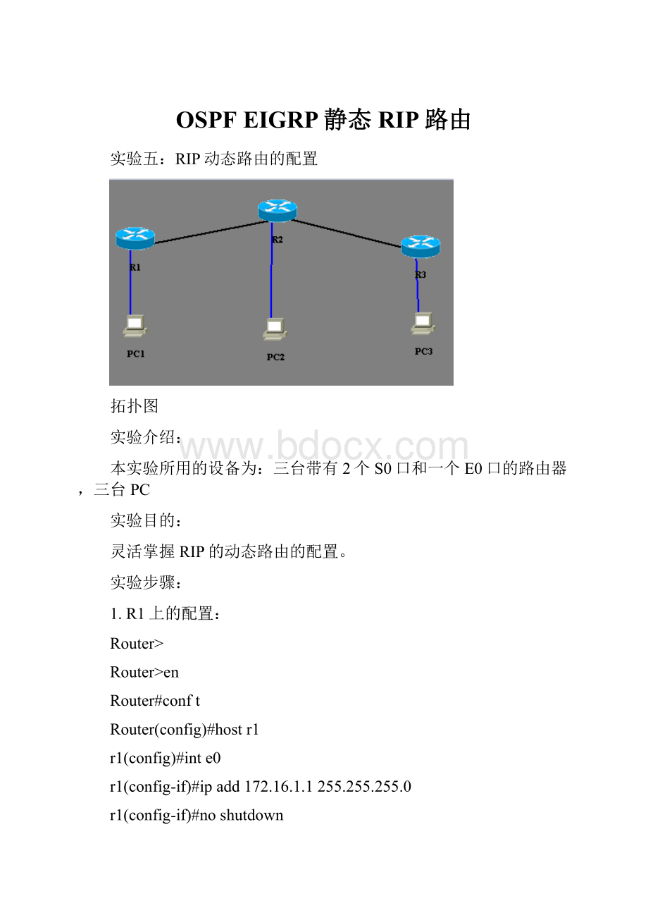
拓扑图
实验介绍:
本实验所用的设备为:
三台带有2个S0口和一个E0口的路由器,三台PC
实验目的:
灵活掌握RIP的动态路由的配置。
实验步骤:
1.R1上的配置:
Router>
Router>en
Router#conft
Router(config)#hostr1
r1(config)#inte0
r1(config-if)#ipadd172.16.1.1255.255.255.0
r1(config-if)#noshutdown
r1(config-if)#exit
r1(config)#ints0
r1(config-if)#ipadd172.16.2.1255.255.255.0
r1(config-if)#noshutdown
r1(config-if)#clockrate56000
r1(config-if)#noshutdown
r1(config-if)#exit
r1(config)#routerrip
r1(config-router)#net172.16.0.0
r1(config-router)#^Z
RIP协议启用前的路由表
r1#showiproute
Codes:
C-connected,S-static,I-IGRP,R-RIP,M-mobile,B-BGP
D-EIGRP,EX-EIGRPexternal,O-OSPF,IA-OSPFinterarea
E1-OSPFexternaltype1,E2-OSPFexternaltype2,E-EGP
i-IS-IS,L1-IS-ISlevel-1,L2-IS-ISlevel-2,*-candidatedefault
U-per-userstaticroute
Gatewayoflastresortisnotset
C172.16.1.0/24isdirectlyconnected,Ethernet0
C172.16.2.0/24isdirectlyconnected,Serial0
RIP协议启用后的路由表
r1#showiproute
Codes:
C-connected,S-static,I-IGRP,R-RIP,M-mobile,B-BGP
D-EIGRP,EX-EIGRPexternal,O-OSPF,IA-OSPFinterarea
E1-OSPFexternaltype1,E2-OSPFexternaltype2,E-EGP
i-IS-IS,L1-IS-ISlevel-1,L2-IS-ISlevel-2,*-candidatedefault
U-per-userstaticroute
Gatewayoflastresortisnotset
C172.16.1.0/24isdirectlyconnected,Ethernet0
C172.16.2.0/24isdirectlyconnected,Serial0
R172.16.3.0/24[120/1]via172.16.2.2,00:
01:
37,Serial0
R172.16.4.0/24[120/1]via172.16.2.2,00:
07:
21,Serial0
R172.16.5.0/24[120/2]via172.16.2.2,00:
05:
21,Serial0
2.R2上的配置:
Router>
Router>en
Router#conft
Router(config)#hostr2
r2(config)#ints1
r2(config-if)#ipadd172.16.2.2255.255.255.0
r2(config-if)#noshutdown
r2(config-if)#exit
r2(config)#ints0
r2(config-if)#ipadd172.16.4.0255.255.255.0
r2(config-if)#ipadd172.16.4.1255.255.255.0
r2(config-if)#clockrate56000
r2(config-if)#noshutdown
r2(config-if)#exit
r2(config)#inte0
r2(config-if)#ipadd172.16.3.1255.255.255.0
r2(config-if)#noshutdown
r2(config-if)#exit
r2(config)#routerrip
r2(config-router)#net172.16.0.0
r2(config-router)#^Z
r2#showiproute
Codes:
C-connected,S-static,I-IGRP,R-RIP,M-mobile,B-BGP
D-EIGRP,EX-EIGRPexternal,O-OSPF,IA-OSPFinterarea
E1-OSPFexternaltype1,E2-OSPFexternaltype2,E-EGP
i-IS-IS,L1-IS-ISlevel-1,L2-IS-ISlevel-2,*-candidatedefault
U-per-userstaticroute
Gatewayoflastresortisnotset
C172.16.2.0/24isdirectlyconnected,Serial1
C172.16.3.0/24isdirectlyconnected,Ethernet0
C172.16.4.0/24isdirectlyconnected,Serial0
R172.16.1.0/24[120/1]via172.16.2.1,00:
09:
13,Serial1
R172.16.5.0/24[120/1]via172.16.4.2,00:
09:
13,Serial0
3.R3上的配置:
Router>
Router>en
Router#conft
Router(config)#ints1
Router(config-if)#ipadd172.16.4.2255.255.255.0
Router(config-if)#noshutdown
Router(config-if)#exit
Router(config)#inte0
Router(config-if)#ipadd172.16.5.1255.255.255.0
Router(config-if)#noshutdown
Router(config-if)#exit
Router(config)#hostr3
r3(config)#
r3(config)#routerrip
r3(config-router)#net172.16.0.0
r3(config-router)#^Z
r3#showiproute
Codes:
C-connected,S-static,I-IGRP,R-RIP,M-mobile,B-BGP
D-EIGRP,EX-EIGRPexternal,O-OSPF,IA-OSPFinterarea
E1-OSPFexternaltype1,E2-OSPFexternaltype2,E-EGP
i-IS-IS,L1-IS-ISlevel-1,L2-IS-ISlevel-2,*-candidatedefault
U-per-userstaticroute
Gatewayoflastresortisnotset
C172.16.4.0/24isdirectlyconnected,Serial1
C172.16.5.0/24isdirectlyconnected,Ethernet0
R172.16.1.0/24[120/1]via172.16.4.1,00:
05:
32,Serial1
R172.16.2.0/24[120/1]via172.16.4.1,00:
08:
19,Serial1
R172.16.3.0/24[120/1]via172.16.4.1,00:
05:
32,Serial1
4.测试:
r1#
r1#ping
Protocol[ip]:
TargetIPaddress:
172.16.5.2
Repeatcount[5]:
Datagramsize[100]:
Timeoutinseconds[2]:
Extendedcommands[n]:
Typeescapesequencetoabort.
Sending5,100-byteICMPEchosto172.16.5.2,timeoutis2seconds:
!
!
!
!
!
Successrateis100percent(5/5),round-tripmin/avg/max=1/2/4ms
PC上的配置为:
PC1:
IP为172.16.1.2网关:
172.16.1.1
PC2:
IP为172.16.3.2网关:
172.16.3.1
PC3:
IP为172.16.5.2网关:
172.16.5.1
实验四:
静态路由、缺省路由的配制
实验目的:
三台路由连接5个网段,配置静态路由和缺省路由
拓扑图:
Router>en
Router#conft
Router(config)#hostR1
R1(config)#inte0进入e0端口
R1(config-if)#ipadd172.16.3.1255.255.255.0添加e0口的IP
R1(config-if)#noshut打开e0口
R1(config-if)#exit
R1(config)#ints0进入s0端口
R1(config-if)#ipadd172.16.1.1255.255.255.0添加s0口的IP
R1(config-if)#clockrate56000设置时钟
R1(config-if)#noshut打开s0口
R1(config-if)#exit
R1(config)#iproute0.0.0.00.0.0.0172.16.1.2添加缺省路由
Router>en
Router#conft
Router(config)#hostR2
R2(config)#inte0进入e0端口
R2(config-if)#ipadd172.16.4.1255.255.255.0添加e0口的IP
R2(config-if)#noshut打开e0口
R2(config-if)#exit
R2(config)#ints1进入s1端口
R2(config-if)#ipadd172.16.1.2255.255.255.0添加s1口的IP
R2(config-if)#noshut打开s1口t
R2(config-if)#exit
R2(config)#iproute172.16.3.0255.255.255.0172.16.1.1添加静态路由
R2(config)#iproute172.16.5.0255.255.255.0172.16.2.2添加静态路由
Router>en
Router#conft
Router(config)#hostR3
R3(config)#inte0进入e0端口
R3(config-if)#ipadd172.16.5.1255.255.255.0添加e0口的IP
R3(config-if)#noshut打开e0口
R3(config-if)#exit
R3(config)#ints1进入s1端口
R3(config-if)#ipadd172.16.2.2255.255.255.0添加s1口的IP
R3(config-if)#noshut打开s1口t
R3(config-if)#exit
R3(config)#iproute0.0.0.00.0.0.0172.16.2.1添加缺省路由
实验9:
RipV1的有类路由实验。
要求:
DEC在s0端口,启用rip路由协议.
R1配置:
En
Conft
HostR1
intlo1
ipadd1.1.1.1255.255.255.0
noshut
Exit
Ints0
Ipadd192.168.1.1255.255.255.0
Clockrate56000
Noshut
R2配置:
Conft
HostR2
Ints1
Ipadd192.168.1.2255.255.255.0
noshut
Exit
Ints0
Ipadd192.168.2.1255.255.255.0
Clockrate56000
noshut
R3配置:
Conft
HostR1
intlo1
ipadd1.1.2.1255.255.255.0
noshut
Exit
Ints1
Ipadd192.168.2.1255.255.255.0
Noshut
添加rip路由
R1:
Routerrip
Network1.0.0.0
Network192.168.1.0
R2:
Routerrip
Network192.168.1.0
Network192.168.2.0
R3:
Routerrip
Network1.0.0.0
Network192.168.2.0
配置完成后,我在路由器模拟器上进行实验,但发现模拟器无论是从R3pingR1的lo1口还是R1pingR3的lo1口都能Ping通,我换到R2继续PingR1的lo1口或是R3的lo1口都能全部Ping通,和崔老师的演示结果不一至,估计是是这个模拟器的软件问题,无法看出实验的真正结果.
正确结果:
R2pingPingR1的lo1口或是R3的lo1口时,发出去的包应该一个能到达一个无法到达,而R3无法PING通R1的lo1口,而R1也一样PING通R3的lo1口.
原因:
因为使用了RIP路由,RIP是有类路由,当R1发现1.0.0.0和192.168.1.0不是同类网段,会进行汇总,告诉R2自己汇总的路由,这样R2会知道R1有1.0.0.0和192.168.1.0两个网段,而R3也是同样原因告诉R2自己1.0.0.0和192.168.2.0两个网段,这时候R2会知道R1和R3同时拥有1.0.0.0网段,所以无论是ping1.1.1.1还是ping1.1.2.1会一个包发向R1下一个包就会发向R3,所以会出现一个包通,另一个包不通的结果.
而R1无法拼通1.1.2.1是因为,R1看自己的汇总路由发现这个地址就是在自己的网段里,就不会向外发,所以无法ping通.R3无法拼通1.1.1.1也是同样的原因.
扩展实验:
更改R1/R2/R3的各个端口.
R1S01.1.3.1/24
R2S11.1.3.2/24
S01.1.4.1/24
R3S11.1.4.2/24
配置:
R1:
En
Conft
Ints0
Noipadd192.168.1.1255.255.255.0
Ipadd1.1.3.1255.255.255.0
Noshut
Exit
Routerrip
Nonetwork192.168.1.0
Network1.0.0.0
R2:
En
Conft
Ints1
Noipadd192.168.1.2255.255.255.0
Ipadd1.1.3.2255.255.255.0
Noshut
Exit
Ints0
Noipadd192.168.2.1255.255.255.0
Ipadd1.1.4.1255.255.255.0
Noshut
exit
Routerrip
Nonetwork192.168.1.0
Nonetwork192.168.2.0
Netwokr1.0.0.0
Network1.0.0.0
R3:
En
Conft
Ints1
Noipadd192.168.2.1255.255.255.0
Ipadd1.1.4.2255.255.255.0
Noshut
Exit
Routerrip
nonetwork192.168.2.0
Network1.0.0.0
结果:
通过一系列的IP改变,前一个实验中出现的问题全部都解决了无论是R2pingR1的lo1还是pingR3的lo1口都不会出现丢包的现象.而R1也能ping通R3的lo1口,R3同样也能ping通R3的lo1口.
原因:
因为每台路由器中的IP地址都是同网段,连续子网的有类路由,所以路由路没有起用汇总,就不会出现原来的问题,R1不会以为R3的lo1口就在自己网段,R3一样也不会以为R1的lo1口在自己网段,而R2也不会认为R1和R3在同一网段而不知道发给谁了.
实验14OSPF缺省路由协议配置
实验目的:
1.对ospf的概念有所了解。
OSPF(OpenShortestPathFirst)是一个内部网关协议(InteriorGatewayProtocol,简称IGP),一个链路状态路由选择协议,用于在单一自治系统(autonomoussystem,AS)内决策路由。
OSPF通过路由器之间通告网络接口的状态来建立链路状态数据库,生成最短路径树,每个OSPF路由器使用这些最短路径构造路由表
2学习使用身份验证
为了安全的原因,我们可以在相同OSPF区域的路由器上启用身份验证的功能,只有经过身份验证的同一区域的路由器才能互相通告路由信息。
在默认情况下OSPF不使用区域验证。
通过两种方法可启用身份验证功能,纯文本身份验证和消息摘要(md5)身份验证。
纯文本身份验证传送的身份验证口令为纯文本,它会被网络探测器确定,所以不安全,不建议使用。
而消息摘要(md5)身份验证在传输身份验证口令前,要对口令进行加密,所以一般建议使用此种方法进行身份验证。
使用身份验证时,区域内所有的路由器接口必须使用相同的身份验证方法。
为起用身份验证,必须在路由器接口配置模式下,为区域的每个路由器接口配置口令。
任务
命令
指定身份验证
areaarea-idauthentication[message-digest]
使用纯文本身份验证
ipospfauthentication-keypassword
使用消息摘要(md5)身份验证
ipospfmessage-digest-keykeyidmd5key
3.了解ospf缺省路由协议配置的基本方法。
配置步骤:
Router1:
en
conft
hostR1
ints0/*进入s0端口*/ipadd2.2.2.1255.255.255.0/*添加s0口ip*/
noshut
clockrate56000
ipospfmessage-digest-key1md5cisco
exit
ints1/*进入s1端口*/
ipadd5.5.5.1255.255.255.0/*添加s1口ip*/
noshut
clockrate56000
ipospfmessage-digest-key1md5cisco
exit
intlo1
ipadd1.1.1.1255.255.255.0
exit
routerospf100
net2.2.2.00.0.0.255area0
net5.5.5.00.0.0.255area0
area0authenticationmessage-digest
Router2:
en
conft
hostR2
ints1/*进入s1端口*/
ipadd2.2.2.2255.255.255.0/*添加s1口ip*/
noshut
ipospfmessage-digest-key1md5cisco
exit
ints0/*进入s0端口*/
ipadd3.3.3.1255.255.255.0/*添加s0口ip*/
clockrate56000
ipospfmessage-digest-key1md5cisco
noshut
exit
ints2
ipadd6.6.6.2255.255.255.0
exit
routeospf100
default-informationoriginate
exit
iproute0.0.0.00.0.0.03.3.3.2/*添加缺省路由*/
routerospf100
net2.2.2.10.0.0.0area0
net3.3.3.00.0.0.255area0
net6.6.6.10.0.0.0area0
area0authenticationmessage-digest
Router3:
en
conft
hostR3
ints1/*进入s1端口*/
ipadd3.3.3.2255.255.255.0/*添加s1口ip*/
noshut
ipospfmessage-digest-key1md5cisco
exit
intlo1
ipadd4.4.4.1255.255.255.0
exit
routerospf100
net3.3.3.10.0.0.0area0
area0authenticationmessage-digest
Router4:
en
conft
hostR4
ints0/*进入s0端口*/
ipadd5.5.5.2255.255.255.0/
 升级会员
升级会员 