道路撞击检测系统中英文对照外文翻译文献Word文档下载推荐.docx
《道路撞击检测系统中英文对照外文翻译文献Word文档下载推荐.docx》由会员分享,可在线阅读,更多相关《道路撞击检测系统中英文对照外文翻译文献Word文档下载推荐.docx(10页珍藏版)》请在冰豆网上搜索。
通过使用高速GPS[1]和单片机控制算法,认识到对于线性扫描式照相机的实时控制根据每2毫米产生一触发信号。
这一检测结果满足该系统的要求,与此同时获得了更为清晰的道路动态图像。
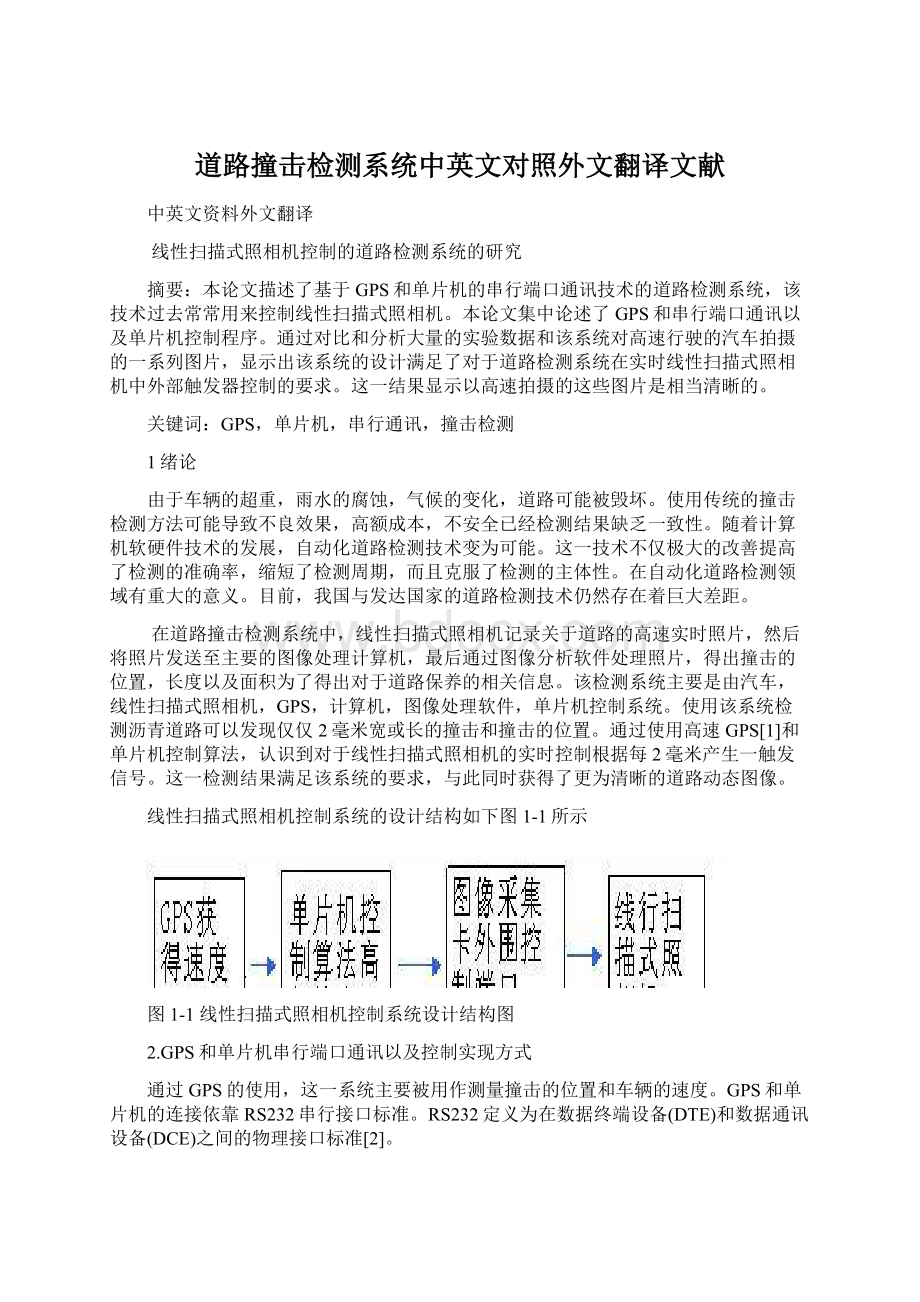
线性扫描式照相机控制系统的设计结构如下图1-1所示
图1-1线性扫描式照相机控制系统设计结构图
2.GPS和单片机串行端口通讯以及控制实现方式
通过GPS的使用,这一系统主要被用作测量撞击的位置和车辆的速度。
GPS和单片机的连接依靠RS232串行接口标准。
RS232定义为在数据终端设备(DTE)和数据通讯设备(DCE)之间的物理接口标准[2]。
单片机串行端口初始化程序依靠特殊功能寄存器PCON和功率控制寄存器SCON。
SCON串行端口被用作设置工作模式,接收或发送控制/状态信号。
串行端口有四种工作模式。
该系统使用工作模式2。
由于安装了波特率为4800的GPS,不再需要计算它。
通讯模式采用8-N-1。
GPS定位模式有2种。
一种是信号点定位模式,另一种是不同的定位模式。
信号点定位方式一直使用一个GPS接收器为了接收3或4个卫星信号以便于确定接收信号的位置。
但是它的错误率相对比较高,甚至高达5~15米。
GPS有不同种类的数据格式,通常我们在数据的开头使用$GPRMC格式,设置它作为标准接收数据格式。
GPS使用RS232来传输数据,所以我们应该在GPS和SCM之间添加一个MAX232来完成逻辑标准转换。
转换后的数据被直接传输到SCM后,该系统能够获得车辆的速度值。
电路设计如下图2-1所示。
图2-1GPS&
SCM串行通讯接口电路设计
该系统采用COM1传输数据,波特率为4800。
单片机串行端口采用工作方式2。
以下是部分执行程序:
TMOD=0x20;
//定时器1工作模式2(主要用于定时)
TL1=0xf3;
11
TH1=0xf3;
SCON=0x50;
PCON=0x00;
IE=0x90;
//串行端口中断许可
TR1=1;
}串行()中断4使用1//串行端口中断服务功能实现
{RI=0;
//软件清除中断标记
if(SBUF==0x24)
{num++;
record=1;
i=0;
k=0;
r=1;
igps=0;
//记录速度数据的数字
numbercoma=0;
if(record==1)//Begintojudgewhetherthedatareceived开始判断这一数据是否接受GPRMC格式
{s="
GPRMC"
;
string[k]=SBUF;
k++;
r=strcmp(string,s);
if(r==0)
{if(SBUF==0x2c){numbercoma++;
}//记录逗号的个数
if(numbercoma==2)
{if(SBUF==0x41)//如果第二个判断是A,那么数据有效
{if(numbercoma==7)//位于第七个逗号后的字符代表速度信号{stringgps[igps]=SBUF;
//将这个字符赋予字符串"
stringgps"
中
igps++;
}}}//thefirstcommandisoverwhenreceivethesecond$,Variablegiventheinitialvalue当接受到赋予初值的第二个$时第一条命令结束
if(num==2){stringgps[igps]='
\0'
//Theendofthedatapresentedattheendofthestring字符串结束标志位
num=0;
Record=0;
igps=0;
//当变量为零时重新接受速度数据
3单片机控制的实时行扫描照相机
单片机控制的实时行扫描照相机使用单片机89C51[3]微控制机。
由于每两毫米产生一个触发信号的需要给照相机,该系统使用计时器来控制单片机中的触发时间,显示来自依靠串行通讯的GPS的车辆速度[4]。
它使用该单片机的T1计时器来计时。
计时器的模式采用模式1。
它需要计算间隔时间,该时间是2毫米的触发器根据车辆的速度值所得到的。
在这一模式中,该系统预先设置时间作为12秒使用计时器T1,依靠P20端口标准输出来实现对于照相机的控制。
该系统使用方式1计时。
该方式能获得更多的计时时间和更大的计时周期。
该检测系统能过满足照相机工作频率的要求[5]。
通过使用软件来控制TF1和TR1能够得到最好的计时器输入和输出,这意味着依靠计时器的时间和计时周期来控制触发器信号。
该系统选择计时器1的模式1工作。
振晶为12MHz。
机器周期为1μs,预设时间周期为12μs,接着12μs=(2-Y)*1μs,然后计算初始计时值Y作为65,524,将这一值放进16位计时器,接受启动T1计时器。
当计时时间为12μs时结束,TF1=1。
根据不同的速度值和公式:
x=3000/v,计算周期时间和为了控制照相机的工作频率获得P20高低水平控制。
{
intv=35;
intx;
//加入速度值,作为一变量
x=(3000)/(v);
//计算周期时间
led_on();
time_lms(x);
led_off();
}
while
(1);
time_lms(lms)
{TMOD=TMOD&
(0x0f)|0x10;
TR1=1;
//开始计时
While(lms--)
{TH1=65524/256;
TL1=65524/256;
While(!
TF1)
TF1=1;
TR1=0;
led_off(){P2_0=1;
led_on()
{P2_0=0;
3图像分析和对比
系统使用GPS为了定位起始位置并且将道路公里数结合于标记精确的道路撞击地点[6]。
由于该系统需要在车辆运行时拍摄道路的动态照片,同时需要满足每两毫米拍摄一帧图片的要求,因此该系统需要控制线性扫描式照相机的工作频率以获得实时照片。
该系统使用GPS为了获得车辆的速度值,并且通过串行通讯传输该速度值至单片机控制系统以实现每两毫米拍摄一帧照片的照相机控制。
由于该系统采用线性排列的照相机,它需要在每毫米的距离提供一个触发信号来满足两毫米宽度路面撞击的检测精度要求[7]。
如果该系统并未采用实时控制照相机的工作频率,那么线性扫描式照相机接受到的大部分照片是不清晰的。
由于车辆在行驶中的速度总是不断变化的,使用该论文中设计的控制系统将获得更加清晰路面照片[8]。
采用恒定的频率采集方式将达不到如此清晰的动态照片。
该论文设计的系统满足道路撞击检测精度要求。
与此同时下面的图片提供了可靠的根据。
图3-1和图3-2是拍摄的两张道路检测的照片案例。
图3-1实时控制照相机采集的照片
图3-2非实时照相机采集的照片
4结论
该系统设计实现了以下功能:
(1)该系统通过硬件和软件的设计实现了速度值的测量,并且设计了控制GPS和单片机串行通讯的程序[9]。
(2)根据车辆的速度值程序控制P20单片机端口输出电压以监控线性扫描式实时照相机的工作频率。
(3)该系统使道路撞击检测精确度要求达到了2毫秒级别的精度,并且能够获得十分清晰的动态图片以至在公路检测方面达到很好的效果。
(4)通过对比采集照片的质量和大量的外围实验数据显示,该设计系统能够在车辆高速行驶的情况下获得清晰的动态照片。
Line-ScanCameraControlPavementDetection
SystemResearch
Abstract.Thepaperdesignsthepavementdetectingsystem,whichisbasedonGPSandtheserialportcommunicationtechnologyoftheSCM(single-chipmicrocomputer)usedtocontroltheline-scancamera.ThepaperfocusesonGPSandtheserialportcommunicationaswellasthecontrolprogramsofsinglechipmicrocomputer.Bycomparingandanalyzinglargeamountsofexperiments’dataandtheserialimageswhichareobtainedinthehigh-speedvehiclemovingbyusingthissystem,itshowsthatthissystemdesignsatisfiestherequirementofexternaltriggercontrolinreal-timeline-scancameraforthepavementdetectionsystem.Theresultshowsthattheimagesobtainedinhighspeedaremuchclearer.
Keywords:
GPS;
single-chipmicrocomputer;
serialcommunication;
crackdetection.
1Introduction
Becauseoftheoverweightofvehicles,rainerosion,climatechange,thepavementmaybedestroyed.Usingtraditionalcrackdetectingmethodsmayleadtolowefficiency,highcost,insecurityandpoorconsistencyofdetectingresults.Withthedevelopmentofcomputerhardwareandsoftwaretechnology,automaticpavementdetectiontechnologybecomespossible.Itnotonlygreatlyimprovesthedetectionrate,shortensthedetectingcycle,butalsoovercomesthesubjectivityofthedetecting.Ithasgreatsignificanceintheautomaticpavementdetectionfield.Atpresent,thereisstillawidegapbetweenChina'
sroaddetectingtechnologyandthedevelopedcountries’.Inthepavementcrackdetectionsystem,theline-scancamerafirstcaptureshighspeedreal-timeimagesabouttheroad,thensendsittothemainimageprocessorcomputer,atlastprocessesitwithimageanalysissoftware,getthecrack’splace,lengthandareasoastogivereferencetotheroadmaintenance.Detectionsystemiscomposedofthevehicle,line-scancamera,GPS,computer,imageprocessingsoftware,SCMcontrolsystem.Detectingtheasphaltpavementbyuseofthesystemcanfindthecrackwhichismorethantwomillimeters,includingitswidth,lengthandlocations.ByusingthespeedofGPS[1]andSCMcontrolalgorithms,itrealizestherealtimecontrolforline-scancameraaccordingtoeverytwomillimeterstogiveaLine-ScanCameraControlPavementDetectionSystemResearch9triggeringsignal.Thedetectingresultsmeettherequirementsofthesystem,meanwhile,obtainmuchclearerpavementmovingimages.Thedesignstructureofline-scancameracontrolsystemisshowninFig1.
Fig1.Line-scancameracontrolsystemdesignstructure
2GPSandSCMSerialPortCommunicationasWellasControlRealizingMethod
ByusingGPS,thesystemismainlyusedtoobtainthecracklocationandthespeedofthevehicle.ThelinkbetweenGPSandSCMdependsontheRS232serialinterfacestandard.RS232definesthephysicalinterfacestandardsbetweenthedataterminalequipment(DTE)andthedatacommunicationsequipment(DCE)[2].SCMserialportinitializesprogrammingfinishedbythespecialfunctionregisterPCONandpowercontrolSCONregister.SCONserialportisusedtosettheworkingmodes,acceptorsendthecontrol/statesignal.Theserialporthasfourworkingmodes.Thissystemusesworkingmode2.BecausetheGPS4800baudrateisfixed,thereisnoneedtocalculateit.Communicationmodeadopts8-N-1.GPSlocatingmethodhastwomodes.Oneisasinglepointlocatingmode.Theotheroneisdifferentiallocatingmode.Single-pointapproachisusingaGPSreceivertoreceivethreeorfoursatellitesignalssoastodeterminethelocationofreceivingpoints.Butitserrorislargerrelatively,evenupto5~15m.GPShasseveralkindsofdataformats,typicallyweuse$GPRMCatthebeginningofthedata,setitasthestandardreceivingdataformat.GPSusestheRS232totransferdata,soweshouldplusaMAX232betweenGPSandSCMtofinishlogiclevelconversion.AftertheconversiondatacanbedirectlytransmittedtotheSCM,thesystemcanobtainthespeedvalueofthevehicle.ThecircuitdesignisshowninFig.2.
Fig.2.GPS&
SCMserialcommunicationinterfacecircuitdesign
Thesystemadoptscom1totransferdata.Thebaudrateis4800.SCMserialport
adoptsthemode2towork.Partoftherealizingprogramisasfollows:
TMOD=0x20;
//timer1workingmode2(mainlyusedfortiming)
TL1=0xf3;
TH1=0xf3;
SCON=0x50;
PCON=0x00;
IE=0x90;
//serialportinterruptpermitting
}serial()interrupt4using1//Serialportinterruptservicefunction
{RI=0;
//softwareclearinterruptindex
//variablesRecordingnumberofcharacters
speeddata
if(record==1)//Begintojudgewhetherthedatareceived
GPRMCformat
}//recordthenumbersofcomma
{if(SBUF==0x41)//ifthesecondjudgeisA,thenthedataisvalid
{if(numbercoma==7)//thecharacterfollowedtheseventhcommaisspeedsignal
{stringgps[igps]=SBUF;
//putthecharacterintothestring"
}}}//thefirstcommandisoverwhenreceivethesecond$,Variablegiven
theinitialvalue
//Theendofthedatapresentedattheendofthe
string
//restartreceivingspeeddatawhen
Variablegetzero.
3SCMControltheLine-ScanCamerainReal-Time
SCMcontrolstheline-scancamerainreal-timebyusingSCM89C51[3]microcontroller.Duetotheneedofeverytwomillimeterstogiveatriggersignaltothecamera,thesystemusestimertocontrolthetriggertimeinSCM,readsthevehicle’sspeedfromtheGPSbyserialcommunication[4].ItusestheSCMT1timertotime.Thetimingmodeadoptsmode1.Itneedstocalculatetheintervaltimerequiredby2millimeterstotriggeraccordingtothevehicle’sspeedvalue.Inthismethod,thesystempresetstimetobe12secondsbyusingtimers’T1,dependsontheP20portleveloutputtorealizethecontrolforcamera.Thesystemusesmanner1totime.Thismodecangetmuchtimingtimeandmoretimingcycles.
 升级会员
升级会员 