整流器论文中英文资料外文翻译文献Word文档格式.docx
《整流器论文中英文资料外文翻译文献Word文档格式.docx》由会员分享,可在线阅读,更多相关《整流器论文中英文资料外文翻译文献Word文档格式.docx(16页珍藏版)》请在冰豆网上搜索。
Transforming
(1)intothe–referenceframeusing(4)
(5)
wherepisadifferentialoperatorand.
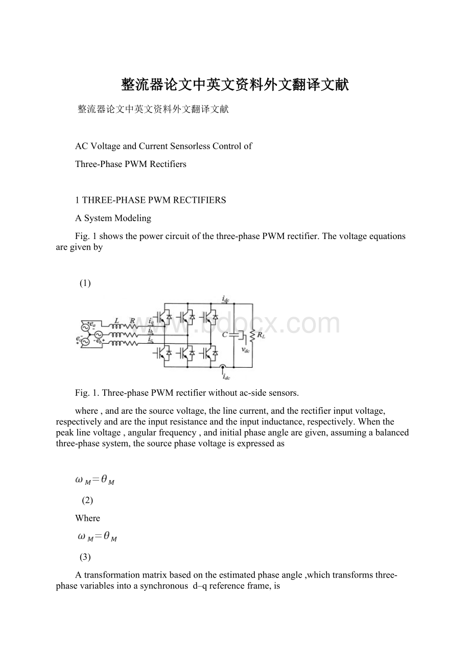
Expressing(5)inavectornotation
(6)
where,
(7)
Takingatransformationof
(2)byusing(4)
(8)
(9)
Expressing(6)and(8)inadiscretedomain,byapproximatingthederivativetermin(6)byaforwarddifference[9],respectively,
(10)
(11)
WhereTisthesamplingperiod.
Fig.2.Overallcontrolblockdiagram.
BSystemControl
ThePIcontrollersareusedtoregulatethedcoutputvoltageandtheacinputcurrent.Fordecouplingcurrentcontrol,thecross-couplingtermsarecompensatedinafeedforward-type
andthesourcevoltageisalsocompensatedasadisturbance.Fortransientresponseswithoutovershoot,theanti-winduptechniqueisemployed[10].TheoverallcontrolblockdiagrameliminatingthesourcevoltageandlinecurrentsensorsisshowninFig.2.Theestimationalgorithmofsourcevoltagesandlinecurrentsisdescribedinthefollowingsections.
2PREDICTIVECURRENTESTIMATION
Thecurrentsof
and
cannotbecalculatedinstantlysincethecalculationtimeoftheDSPisrequired.Toeliminatethedelayeffect,astateobservercanbeused.Inaddition,thestateobserverprovidesthefilteringeffectsfortheestimatedvariable.
Expressing(5)inastate-spaceform,
(12)
(13)
where,
Andyistheoutput.
Transforming(12)and(13)intoadiscretedomain,respectively,
(14)
(15)
Then,theobserverequationaddinganerrorcorrectiontermtoisgivenby
(16)
WhereKistheobservergainmatrixand“^”meanstheestimatedquantity,and
isthestatevariableestimatedaheadonesamplingperiod.Subtracting(15)from(16),theerrordynamicequationoftheobserverisexpressedas
(17)
where
.Here,itisassumedthatthemodelparametersmatchwellwiththerealones.Fig.3showstheblockdiagramoftheclosed-loopstateobserver.
Thestatevariableerrordependsonlyontheinitialerrorandisindependentoftheinput.For(17)toconvergetothezerostate,therootsofthecharacteristicequationof(17)shouldbelocatedwithintheunitcircle.
Fig.3.Closed-loopstateobserver.
Fig.4.Shortpulseregion.
4EXPERIMENTSANDDISCUSSIONS
A.SystemHardwareConfiguration
Fig.5showsthesystemhardwareconfiguration.Thesourcevoltageisathree-phase,110[V].Theinputresistanceandinductanceare0.06Ωand3.3mH,respectively.Thedclinkcapacitanceis2350μFandtheswitchingfrequencyofthePWMrectifieris3.5kHz.
Fig.5.Systemhardwareconfiguration.
Fig.6.Dclinkcurrentsandcorrespondingphasecurrents(insectorV).
TheTMS320C31DSPchipoperatingat33.3MHzisusedasamainprocessorandtwo12-bA/Dconvertersareused.Oneofthemisdedicatedfordetectingthedclinkcurrentandtheotherisusedformeasuringthedcoutputvoltageandthesourcevoltagesandcurrents,whereacsidequantitiesarejustmeasuredforperformancecomparison.
OneoftwointernaltimersintheDSPisemployedtodecidethePWMcontrolperiodandtheotherisusedtodeterminethedclinkcurrentinterrupt.Consideringtherectifierblankingtimeof3.5s,A/Dconversiontimeof2.6s,andtheothersignaldelaytime,theminimumpulsewidthissetto10s.
A.ExperimentalResults
Fig.6showsmeasureddclinkcurrentsandphasecurrents.IncaseofsectorVofthespacevectordiagram,thedclinkcurrentcorrespondstofortheswitchingstateofandforthatof.Fig.7(a)showstherawdclinkcurrentbeforefiltering.Ithasalotofringingcomponentsduetotheresonanceoftheleakageinductanceandthesnubbercapacitor.Whenthedccurrentissampledattheendpointoftheactivevoltagevectorsasshowninthefigure,themeasuringerrorcanbereduced.
Fig.7.Samplingofdclinkcurrents.
Fig.8.Estimatedsourcevoltageandcurrentatstarting.
Toreducethiserrorfurther,thelowpassfiltershouldbeemployed,ofwhichresultisshowninFig.7(b).Thecut-offfrequencyoftheButterworth’ssecond-orderfilteris112kHzanditsdelaytimeisabout2sec.Sincetheringingfrequencyis258kHzandtheswitchingfrequencyis3.5[kHz],thefilteredsignalwithoutsignificantdelayisacquired.
Fig.8showstheestimatedsourcevoltageandcurrentatstarting.Withtheproposedinitialestimationstrategy,thestartingoperationiswellperformed.Fig.9showsthephaseangle,magnitude,andwaveformoftheestimatedsourcevoltage,whichcoincidewellwithmeasuredones.
Fig.10showsthesourcevoltageandcurrentwaveformatunitypowerfactor.Figs.Withtheestimatedquantitiesforthefeedbackcontrol,thecontrolperformanceissatisfactory.Thedcvoltagevariationforloadchangeswillberemarkablydecreasedifafeedforwardcontrolfortheloadcurrentisadded,whichispossiblewithoutadditionalcur-rentsensorwhenthePWMrectifieriscombinedwiththePWMinverterforacmotordrives.
Fig.9.Estimatedsourcevoltageinsteadystate.
(a)phaseangle(b)magnitude(c)waveform.
Fig.10.Sourcevoltageandcurrentwaveforms.
(a)estimated(b)measured.
4CONCLUSIONS
ThispaperproposedanovelcontrolschemeofthePWMrectifierswithoutemployinganyacinputvoltageandcurrentsensorsandwithusingdcvoltageandcurrentsensorsonly.Reducingthenumberofthesensorsuseddecreasesthesystemcostaswellasimprovesthesystemreliability.Thephaseangleandthemagnitudeofthesourcevoltagehavebeenestimatedbycontrollingthedeviationbetweentherectifiercurrentanditsmodelcurrenttobezero.Forlinecurrentreconstruction,switchingstatesandmeasureddclinkcurrentswereused.Toeliminatetheeffectofthecalculationtimedelayofthemicroprocessor,thepredictivestateobserverwasused.Itwasshownthattheestimationalgorithmisrobusttotheparametervariation.Thewholealgorithmhasbeenimplementedforaproto-type1.5[kVA]PWMrectifiersystemcontrolledbyTMS320C31DSP.Theexperimentalresultshaveverifiedthattheproposedacsensoreliminationmethodisfeasible.
无交流电动势、电流传感器的三相PWM整流器控制
1三相PWM整流器
A系统模型
图一所示为三相PWM整流器的主电路,电压等式给出如下:
(1)
图1无交流传感器三相PWM整流器
其中e,i和v分别是源电压,线电流和整流器的输入电压,R和L分别是输入电阻和输入电感。
当已知线电压峰值E,角频率
和初始相位角θ时,假定三相系统是平衡的,则源相位电压可以表达为
(2)
其中
一种基于估计相位角
的变换矩阵,将三相变量变换成一个同步的,
坐标系,这个矩阵是
(4)
将
(1)式变为
坐标系使用式(4)
(5)
其中p是一个微分算子且
将(5)式写成矢量形式
(6)
用式(4)对
(2)式进行变换
(8)
(9)
通过前向差分来接近微分的限幅,分别将(6)式和(8)式用离散域表示
(10)
(11)
其中,T是采样周期
图2总的控制模块图
B系统控制
PI控制器是用来调节直流输出电压和交流输入电流的。
对于解耦电流控制,交叉耦合项用前馈式补偿,同时,源电压作为扰动的补偿。
对于没有过调的暂态响应,引入anti-windup技术。
消除源电压和线电流传感器的总的控制模块图如图2所示。
源电压和线电流的估计算法在以后的章节中介绍。
2预测电流估计
由于DSP存在计算时间,所以
和
不能立即计算。
为了消除延迟的影响,可以使用状态监测器。
另外,状态监测器可以对估计变量起到滤波作用。
将式(5)用状态空间形式表达为
Y是输出。
分别将式(12)和式(13)分别变换成离散领域
则加入了误差调整的监测器等式为
其中,k是监测器增益矩阵,“^”是指估计量,
是提前一个采样周期估计的状态变量。
用式(15)和减去式(16),监测器的动态误差等式表述为
(17)
这里,假设模型参数与真实系统吻合的很好。
图7所示是闭环状态监测器的模块图。
状态变量误差仅取决于初始误差,与输入无关。
为了使式(17)趋于零状态,典型等式(17)的根应该限制在单位圆内。
图3闭环状态监测器
图4短脉冲区域
3实验与讨论
A系统硬件构造
图5系统硬件结构
图6直流电流和相应相电流(扇区5).
图5所示是系统的硬件结构图。
源电压是三相110V。
输入电阻和电感分别为0.06Ω和3.3mH。
直流侧电容为2350μF,PWM整流器的开关切换频率为3.5KHZ.使用TMS320C31DSP芯片设定在33.3MHZ作为主处理器,同时用到两个12位的A/D转换器:
一个用来检测直流侧电流,另一个用来检测直流侧输出电压、源电压和电流。
其中直流侧数量只是为了性能比较而测量的。
DSP内部的两个时钟一个是用来决定PWM波的控制周期,另一个是用来决定直流侧电流中断。
考虑到整流器空白时间3.5μS,A/D转换时间2.6μS和其他信号延迟时间,最小脉冲宽度
设定为10μS.
C、实验结果
图6所示是测得的直流侧电流和相电流。
假设空间矢量图的扇区V,直流侧电流
对应于
。
图7(a)所示是滤波之前未经处理的直流侧电流。
因漏电感和缓冲电容的共振,会产生噪声成分。
如图中所示,当采样动态电压矢量末端的直流电流时,测量误差可以减小。
图7直流侧电流采样
图8开始时的估计源电压和电流
为了进一步减少误差,可以使用低通滤波器,结果如图7(b)所示。
Butterworth的第二顺序滤波器的截止频率是112KHZ,开关切换频率为3.5KHZ,所以可以得到没有显著延迟的滤波信号。
图8所示是开始时估计源电压和电流。
使用提出的初始估计策略,开始操作效果很好。
图9所示是估计源电压的相位角、数值和波形。
它们和测量的结果十分吻合。
图10所是在单位功率因数时源电压和电流波形。
当PWM整流器与逆变器相连时,在没有额外电流传感器的情况下对交流汽车驾驶来说是可行的。
图9稳态时的估计源电压.
(a)相位角(b)数值(c)波形
图10源电压和电流波形
(a)估计值(b)测量值
4结论
这篇文章提出了一种PWM整流器新颖的控制方法。
这种方法没有使用任何交流输入电压和电流传感器,而仅仅使用直流电压和电流传感器。
减少传感器数量可以减少系统费用的同时就提高系统的稳定性。
通过控制整流器的电流和它的模型电流的偏差为零,可以估计相位角和源电压的数值。
对于线电流重建,使用开关状态和直流侧电流测量。
为了消除因微处理器计算时间所带来的延迟影响,使用预测状态监测器。
可以看出,估计算法对参数变化是健全的。
整个算法已经通过TMS320C31DSP作为控制器的1.5kVAPWM整流器原型执行。
实验结果证明已经证明了提出的消除交流传感器方案的可行性。
 升级会员
升级会员 