IPCA电子产品检验国际标准文档格式.docx
《IPCA电子产品检验国际标准文档格式.docx》由会员分享,可在线阅读,更多相关《IPCA电子产品检验国际标准文档格式.docx(16页珍藏版)》请在冰豆网上搜索。
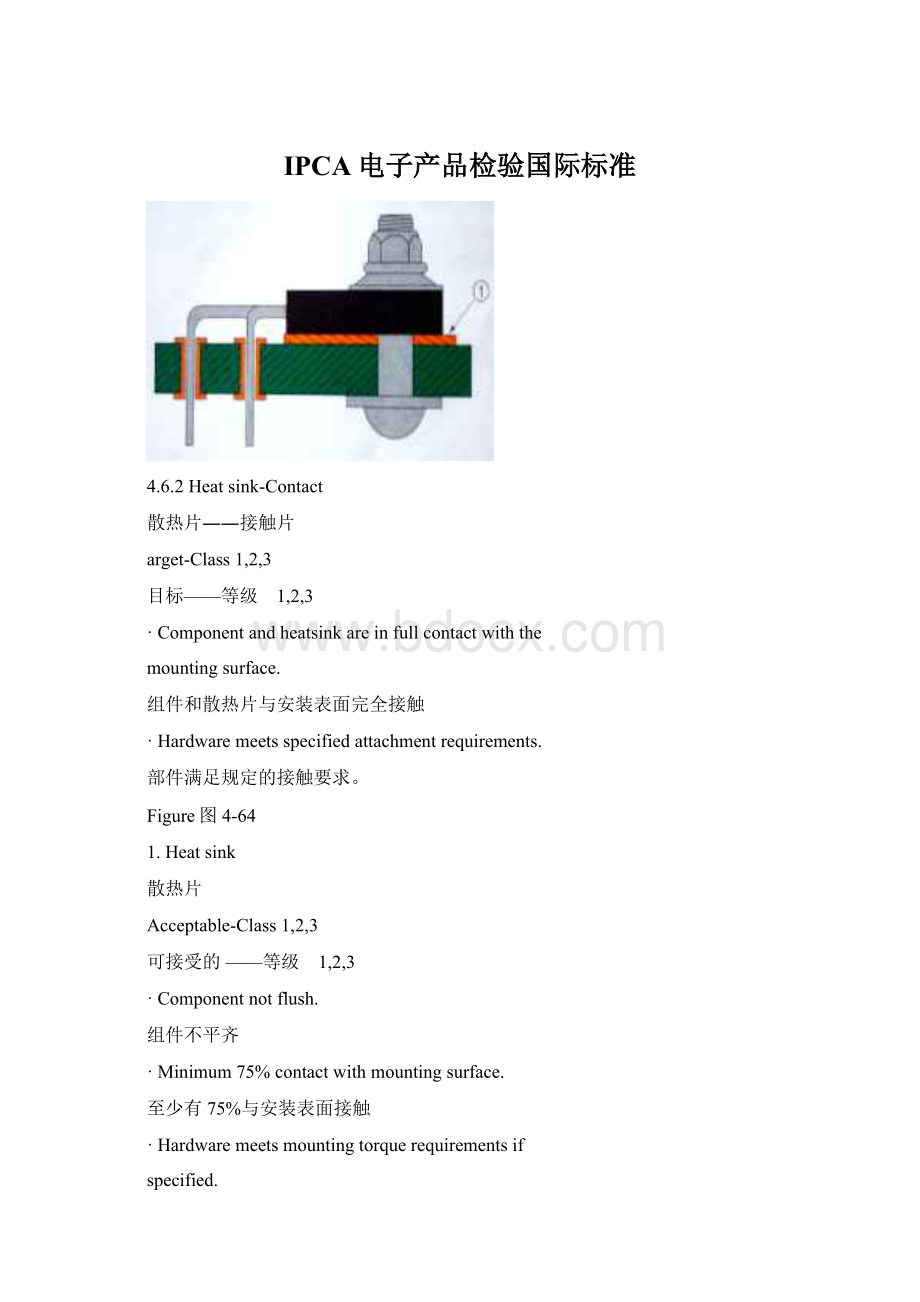
如果有规定,部件满足安装的转距要求
Figure图4-65
1.Gap2.Heatsink
间隙散热片
Defect-Class1,2,3
缺点——等级 1,2,3
Componentisnotincontactwithmountingsurface.
组件没有接触到安装表面
Hardwareislooseandcanbemoved.
部件松弛可以移动。
Figure图4-66
1.Heatsink2.Gap
散热片间隙
5.1Orientation
方向
5.1.1Orientation-Horizontal
方向——水平
Target-Class1,2,3
目标——等级 1,2,3
•Componentsarecenteredbetweentheirlands.
组件位于焊盘中央
•Componentmarkingsarediscernible.
组件标识清晰可见
•Nonpolarizedcomponentsareorientedsothat
markingsallreadthesameway(left-to-right
ortop-to-bottom).
Figure图5-1无极性组件的方向应使其标识都能按同样方式进行辨识
(从左到右或从上到下)
可接受的——等级 1,2,3
•Polarizedandmultileadcomponentsareoriented
correctly.
有极性和多引脚的组件应按正确方向安装。
•Whenhandformedandhand-inserted,polarization
symbolsarediscernible.
当手工成型及手插件时,极性符号可以辨识。
•Allcomponentsareasspecifiedandterminateto
Figure图5-2correctlands.
所有组件都符合规定并连接到正确的焊盘上。
•Nonpolarizedcomponentsdonotneedtobeorientedsothatmarkingsallreadthesameway(left-torightortopto-bottom).
无极性的组件不需要按同样的方向,只要标识可按相同方向辨识即可(从左到右或从上到下).
5.1.1Orientation-Horizontal(cont.)
方向——水平(续)
Defect-Class1,2,3
缺点——等级1,2,3
•Componentisnotasspecified(Wrongpart).
组件不符合规定(组件错误)
•Componentnotmountedincorrectholes.
组件没有安装在正确的孔中。
•Polarizedcomponentmountedbackwards.
有极性组件安装方向相反。
•Multileadedcomponentnotorientedcorrectly.
Figure图5-3多引脚组件的安装方向不正确。
5.1.2Orientation-Vertical
方向——垂直
目标——等级1,2,3
•Nonpolarizedcomponentmarkingsreadfromthetop
down.
无极性组件的标识可以从上至下辨识
•Polarizedmarkingsarelocatedontop.
极性标识位于顶部.
Figure图5-4
Acceptable-Class1,2,3
可接受的——等级1,2,3
•Polarizedpartismountedwithalonggroundlead.
极性组件安装时有长的接地引脚
•Polarizedmarkinghidden.
极性标识被隐藏起来
•Nonpolarizedcomponentmarkingsreadfrombottomto
top.
无极性组件标识可以从底至上辨识。
Figure图5-5
缺点——等级1,2,3
•Polarizedcomponentismountedbackwards.
极性组件安装反向。
Figure图5-6
5.2Mounting
安装
5.2.1Mounting-Horizontal-AxialLeaded-SupportedHoles
安装——水平——轴向引脚——有支撑孔
•Theentirebodylengthofthecomponentisin
contactwiththeboardsurface.
整个组件本体长度与线路板表面完全接触
•Componentsrequiredtobemountedofftheboardare,atleast1.5mm[0.059in]fromtheboardsurface;
e.g.,highheatdissipating.
需要离开线路板表面安装的组件至少要离开线路板
Figure图5-7平面1.5mm(0.059in),如高散热器件.
Figure图5-8
5.2.1Mounting-Horizontal-AxialLeaded-SupportedHoles(cont.)
安装——水平——轴对称引脚——有支撑孔
Acceptable-Class1,2
•Themaximumspacebetweenthecomponentandthe
boardsurfacedoesnotviolatetherequirementsfor
leadprotrusion(see5.2.7)orcomponentheight(H).
Figure图5-9((H)isauser-determineddimension.)
组件与线路板平面之间的最大间距不应违反引脚突出(见5.2.7)或组件高度(H)的要求。
(高度(H)是由使用者决定的尺寸)
ProcessIndicator-Class3
程序指示——等级 3
•Thefarthestdistancebetweenthecomponentbodyandtheboard(D)islargerthan0.7mm[0.028in].
组件本体与线路板之间的最大的距离(D)超过0.7mm(0.028in)。
缺点——等级 1,2,3
•Componentsrequiredtobemountedabovetheboardsurfacearelessthan1.5mm[0.059in]
要求离开线路板表面安装的组件与线路板的距离小于1.5mm(0.059in).
5.2.2Mounting-Horizontal-AxialLeaded-UnsupportedHoles
安装——水平——轴向引脚——无支撑的孔
目标——等级 1.2.3
•Theentirebodylengthofthecomponentisin
整个组件本体长度与线路板表面完全接触.
•Componentsrequiredtobemountedofftheboardare
atminimum1.5mm[0.059in]fromtheboard
Figure图5-10surface;
e.g.,highheatdissipating.
1.NoPlatinginbarrel需要离开线路板表面安装的组件至少要离开线路板平
孔壁上没有电镀面1.5mm(0.059in),如高散热器件.
Componentsrequiredtobemountedofftheboardareprovidedwithleadformsattheboardsurfaceorothermechanicalsupporttopreventliftingofsolderland.
需要离开线路板安装的组件在线路板表面利用引脚形状或其它机械支撑来防止焊盘的翘起。
Figure图5-11Figure图5-12
1.Leadforms
引脚形状
•Componentsrequiredtobemountedofftheboardare
notprovidedwithleadformsattheboardsurface
orothermechanicalsupporttopreventliftingof
solderland.
Figure图5-13
需要离开面板安装的组件在线路板表面未利用引脚的形状或其它机械支撑来防止焊盘翘起
•surfaceComponentsrequiredtobemountedabovetheboardarelessthan1.5mm[0.059in].
要求离开线路板表面安装的组件与线路板的距离小于1.5mm(0.059in)
Figure图5-14
5.2.3Mounting-Horizontal-RadialLeaded
安装——水平——径向引脚
•Thecomponentbodyisinflatcontactwith
theboard'
ssurface.
组件本体与线路板表面平贴接触
•Bondingmaterialispresent,ifrequired.See4.4.
若需要,则可存在粘贴的物质,见4.4
Figure图5-15
•Componentincontactwithboardonatleastone
sideand/orsurface.
组件与线路板至少有一边和/或面接触。
Note:
Whendocumentedonanapprovedassembly
drawing,acomponentmaybeeithersidemounted
orendmounted.Thesideorsurfaceofthebody,orat
leastonepointofanyirregularlyconfigured
component(suchascertainpocketbookcapacitors),needs
Figure图5-16tobeinfullcontactwiththeprintedboard.Thebody
shouldtobebondedorotherwiseretainedtotheboardtopreventdamagewhenvibrationandshockforcesareapplied.
注意:
在被认可的组装图中,一个组件既可能是面安装也可能是边沿安装。
组件体的表面或侧面,或不规则形状组件的至少一点(如某种袖珍电容),需要与印刷线路板完全接触。
组件本体应粘贴或保持在线路板上以防止在震动或撞击时损坏。
•Unbondedcomponentbodynotincontactwith
mountingsurface.
未粘贴的组件本体没有和安装表面接触。
•Bondingmaterialnotpresentifrequired.
在有要求时,却没有粘贴物质。
Figure图5-17
.2.4Mounting-Vertical-AxialLeaded-SupportedHoles
安装——垂直——轴向引脚——有支撑的孔
•Theheightofthecomponentbodyabovetheland,
(H)is0.4mm[0.016in]to1.5mm[0.059in].
组件本体距离焊盘的高度,(H)为0.4mm(0.016in)到
1.5m(0.059in)之间。
•Thecomponentbodyisperpendiculartotheboard.
组件本体与线路板垂直
Figure图5-18•Theoverallheightdoesnotexceedtheheightspecified.
总的高度未超过规定的高度.
•Thecomponentheightabovetheboard,(H)isnot
outsidetherangegiveninTable5-1.
组件距离线路板的高度(H)未超出表5-1给出的范围。
•Theangle(θ)ofthecomponentleaddoesnot
causeaviolationofminimumelectrical
clearance.
组件引脚的角度未产生对最小电气间隙的影响。
Figure图5-19
Table5-1ComponenttoBoardHeight
表5-1组件到线路板的高度
Class1等级1
Class2等级2
Class3等级3
H(min)最小值
0.1mm[0.0039in]
0.4mm[0.016in]
H(max)最大值
6mm[0.24in]
3mm[0.12in]
1.5mm[0.059in]
5.2.4Mounting-Vertical-AxialLeaded-SupportedHoles(cont.)
安装——垂直——轴向引脚——有支撑孔(续)
Acceptable-Class1
可接受的—等级1
ProcessIndicator-Class2,3
过程指示——等级2,3
•Thecomponentmountingheight(H)isgreaterthan
themaximumgiveninTable5-1.
组件安装高度(H)超过了表5-1中给出的最大值。
Figure图5-20Defect-Class1,2,3
•Componentsviolateminimumelectricalclearance.
组件影响到最小电气间隙。
以上仅为整个国际检验规范中的一小部份,整套内容大约为4张光盘,包括了整个电子产业上的国际检验标准。
经过几个月的奋战,终于把一本从国外带回来的英文本翻译成中英文版。
是从事电子研发、制造、检验等部门不可缺少的工具资料!
如果你有这方面的需求,请您与我联系:
 升级会员
升级会员 