北航宇航学院飞设实验报告Word文档格式.docx
《北航宇航学院飞设实验报告Word文档格式.docx》由会员分享,可在线阅读,更多相关《北航宇航学院飞设实验报告Word文档格式.docx(21页珍藏版)》请在冰豆网上搜索。

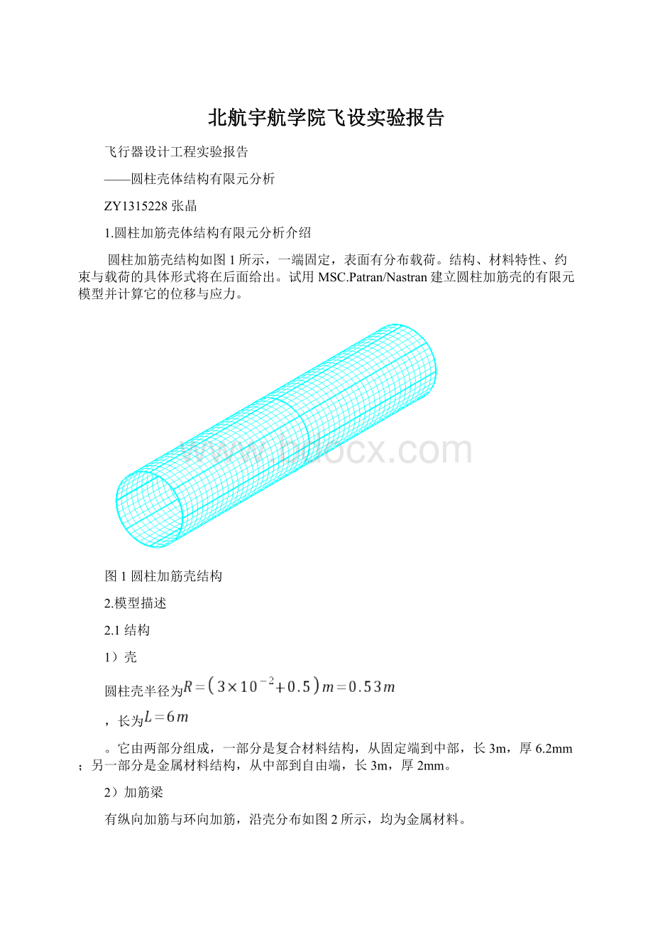
壳的内表面有分布载荷
(Y轴如图3所示)。
3.建模过程
3.1几何模型的建立
1.建立新的数据库,输入全局参数,最大尺寸为6米
File/new
Newdatabasename:
sylindricalshellstructure
Ok
⏹Basedonmodel
Approximatemaximunmodel
Dimesion:
6.0
Analysiscode:
MSC.Nastran
Analysistype:
structure
Ok
2.建立名为”shell”的一个新组
Group/create
Newgroupname:
shell
⏹Makecurrent
Apply
Cancle
3.绘制一半径为0.5m的圆,并通过面拉伸命令形成壳体
⏹Geometry
Actioncreat
Objectcurve
Method2DCircle
Circleradius0.5
Constructionplanelistcoord0.3
Centerpointlist[000]
Actioncreate
Objectsurface
Methodextrude
Tanslationvector<
003>
Curvelistcurve1
4.复制刚刚生成的圆柱壳体
Actiontranform
Objectsurface
Methodtranslate
Surfacelistsurface1
Directionvector<
001>
Vectormagnitude3
Repeatcount1
5.建立一个新的组取名为”circular_beam”
circularbeams
6.通过复制生成另外两个圆形梁曲线
Actiontranform
Objectcircle
Curvelistcurve1
Directionvector<
Repeatcount2
7.纵向筋的绘制,建立一个名为”longitudinalbeams”的新组
longitudinalbeams
8.沿长度方向创建一条直线
Actioncreat
Objectcurve
Methodpoint
Stardingpointpoint1
Endingpointpoint3
9.通过旋转的方法创建8条直线,旋转角度为45°
Actiontransform
Objectcurve
Methodrotate
Rotationangle45
Repeatcount7
Curvelistcurve4
图31几何模型建立完成
1.1显示组”shell”,并设置为当前组
Group/post
Selectgrouptopost:
shell
3.2有限元网格划分
1.将组”shell”设置为当前组
2.生成”meshseed”
⏹Elements
Actioncreate
Objectmeshseed
Typeuniform
Numberofelements:
Number=32
Curvelistcurve1
Number=30
Curvelistsurface1.12.1
3.选择”isomesh”,生成四边形单元
Objectmesh
Typesurface
Elemshapequad
MesherIsoMesh
TopologyQuad4
Surfacelistsurface12
4.显示组“longitudinalbeams”并且设置为当前组
longitudinalbeams
5.用curve的方式划分longitudinalbeams的网格
Actioncreat
Typecurve
Topologybar2
curvelistcurve4:
11
6.显示组“cicularbeams”并设置为当前组
circularbeams
7.用curve的方式划分circularbeams的网格
Objectmesh
Typecurve
Topologybar2
curvelistcurve1:
3
8.节点等效
在面的边上重复创建了节点,因此需要将节点等效
Action:
equivalence
Object:
all
Type:
tolerancecube
Equivalencetolerance:
0.004
Apply
图3-2有限元网格划分完成
3.3材料属性添加
3.3.1复合材料的添加
1.facesheet和core材料添加
⏹Material
create
2dorthotropic
Method:
manualinput
Materialname:
facesheet
Inputproperties
Constitutivemodel:
linearelastic
Elasticmodulus11:
1e11
Elasticmodulus22:
1e10
Poissonratio12:
0.1
Shearmodulus12:
1.5e10
core
Constitutivemodel=:
inearelastic
Elasticmodulus11=:
100
Elasticmodulus22=:
100
0.3
50
Shearmodulus23:
1e6
Shearmodulus13:
图3-3core材料属性
图3-4facesheet材料属性
2.复合材料属性添加,用core和facesheet材料铺成复合材料
create
composite
laminate
compsite_layers
Laminatedcomposite
Materialname
thichness
orientation
1
facesheet
3e-4
45
2
facesheet
-45
core
5e-3
4
5
Inputdate
图3-5复合材料建立完成
3.铜的材料属性添加
isotropic
copper
Elasticmodulus=1e11
Poissionratiao=0.33
4.创建单元属性并将单元属性赋给壳单元
Group/post
shell
⏹Properties
create
2D
shell
Propertysetname:
compositeshell
Options:
lanminlate
m:
composite_layers
Selectmembers:
ele1:
960
coppershell
homogenous
m:
copper
Thickness:
2E-3
ele961:
1920
5.建立本地坐标圆柱系
在壳的地步中心点建立一个本地圆柱坐标系,编号1,用于定义纵向L型梁的指向。
⏹Geometry
Objectcoord
Method3point
CoordIDlist1
Typecylindrical
Refer.Coordinateframecoord1
Origin[000]
Pointonaxis3[001]
Pointonplan1-3[100]
6.创建L型的单元属性并将其赋给L型梁单元
create
1D
beam
Propertysetnamecopper_beam
Inputproperties
Beamlibrary
Actioncreate
Objectstandardshape
Methodnastranstandard
NewsectionnameL
L
W=10e-3
H=10e-3
t1=3e-3
t2=3e-3
Ok
SectionnameL
Materialnamem:
copper
Barorientation<
-100>
coord1
Selectapplicationregion:
ele1921:
2400
Apply
Action:
1D
L-beam
Actioncreate
Newsectionnamerectangle
W=10e-3
Ok
Sectionnamerectangle
ele2401:
2496
3.4固定边界条件建立
⏹Loads/BCs
create
displacement
nodal
Newsetname:
fixed_node
Inputdata
Translation<
T1T2T3>
<
0,0,0>
Rotations<
R1R2R3>
,>
Analysiscoordinateframe:
coord0
Seletapplicaytionregion…
⏹FEM
Applicationregion:
node1:
29:
Add
图3-6固定边界加载完成
3.5建立壳内表面压力场
1.创建一个变化的标量场
⏹Field
create
spatial
pclfunction
Fieldname:
linear_load
Fieldtype:
scalar
Coordinatesystemtype:
Real
Coordinatesystem:
coord0
Scalarfunction:
200*abs(‘Y)
Createthepressureloadthatwillreferencethefieldfunction.
⏹Loads/BCs
pressure
elementuniform
surface_load
Targetelementtype:
2D
Loads/BCssetscalefactor1
Pressure:
Botsurfpressuref:
linear_load
ele1:
图3-7内表面加变化的压力载荷
2.压力载荷和边界条件组装到名为“shell_loads”的工况里面。
⏹Loadcases
Loadcasename:
shell_load
Typestatic
Assign/prioritizeload/BCs:
Disp_fixed_node
Press_shell_load
3.6将建好的模型提交给Nastran分析
⏹Analysi
analyze
entiremodle
fullrun
Jobname:
cylindrical_shell
Solutiontype:
linearstatic
Subcaseselect
Availableloadcases:
3.7读取并查看分析结果
⏹Analysis
accessresults
attachXDB
resultentities
Availablejobs:
Selectresultsfile…
Selectresultsfile:
cylindrical_shell.XDB
⏹Results
quickplot
Selectresultscases:
cylindracal_shell
Selectfringeresult:
stresstensor
Quanlity:
magnitude
Selectdeformationresult:
displacementstranslational
4.结果分析
各部位各层应力—变形图如下
图4-1z1层
图4-2z2层
图4-3复合材料第1层
图4-4复合材料第2层
图4-5复合材料第3层
图4-6复合材料第4层
图4-7复合材料第5层